Allen Bradley 1606-XLDC92D DC/DC Converter Installation Guide
Time:2026-08-11 Browse: 9
Allen Bradley 1606-XLDC92D DC/DC Converter Installation Overview
The Allen Bradley 1606-XLDC92D DC/DC Converter installation process requires correct power evaluation, wiring verification, and commissioning checks to ensure stable operation in industrial automation systems. A proper Installation Guide approach helps prevent common startup problems such as output voltage fluctuation, overload protection activation, and unexpected PLC Controller shutdowns.
The 1606-XLDC92D is widely applied in industrial control panels where stable DC power conversion is required for PLC Controller systems, remote I/O Modules, sensors, and field instruments. Successful installation depends not only on mounting the device but also on understanding the complete power distribution design and System Configuration.
Allen Bradley 1606-XLDC92D DC/DC Converter Role in Industrial Automation
In automation applications, the Allen Bradley 1606-XLDC92D DC/DC Converter provides regulated DC power conversion between the primary supply source and downstream control devices.
Typical applications include:
PLC Controller power circuits
Industrial communication Module power supplies
Remote I/O stations
Sensor and instrumentation networks
Machine control cabinets
The converter must maintain reliable output when the connected load changes. Engineers should consider startup current, continuous load demand, and future system expansion during the initial design stage.
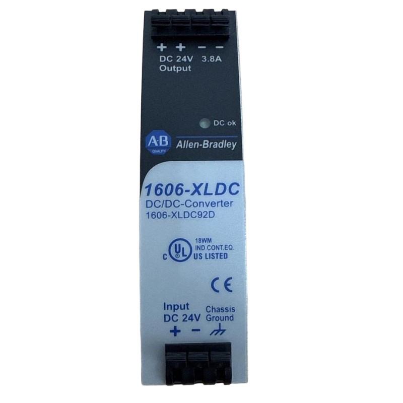
Allen Bradley 1606-XLDC92D Installation Preparation and Power Assessment
Before installing the Allen Bradley 1606-XLDC92D, field engineers should evaluate the electrical environment and confirm that the converter matches the application requirements.
Important preparation tasks include:
Checking DC input voltage stability
Confirming output voltage requirements of connected devices
Calculating total load current
Selecting suitable protection devices
Reviewing cabinet ventilation and installation space
During one commissioning project, a 1606-XLDC92D converter was installed in a control cabinet supplying a PLC Controller and several field sensors. The initial startup showed unstable communication between the controller and remote devices. Engineers measured the input supply and found that the DC source dropped from 24 VDC to 18.7 VDC during actuator startup. After improving the upstream power supply arrangement, the converter operated normally.
This case demonstrates that Installation Guide procedures should include system-level power analysis rather than only device wiring.
Allen Bradley 1606-XLDC92D Wiring and Power Connection Setup
Correct wiring is essential for reliable Allen Bradley 1606-XLDC92D DC/DC Converter operation. In industrial control cabinets, many startup failures are related to reversed polarity, loose terminals, or unstable upstream power sources rather than converter hardware problems.
During installation, engineers should verify the complete power path before energizing the system. The input terminals should be inspected for correct DC polarity, and the measured supply voltage should be compared with the expected operating range. After the converter is powered, the output voltage should be checked both without load and under normal operating conditions.
Field commissioning engineers usually evaluate the converter in the following order:
Confirm DC input voltage and polarity at the converter terminals
Check terminal tightening and cable connection quality
Apply the actual PLC Controller, Module, and Sensor loads
Monitor output voltage stability during machine operation
Record operating values for future Fault Diagnosis reference
In one commissioning case, a newly installed 1606-XLDC92D converter showed normal output voltage during no-load testing but failed after the control system started. The measured output dropped from 24 VDC to 20.1 VDC when several field devices became active. Further inspection found that the connected load current exceeded the original power design. After redistributing the DC loads, the converter maintained stable output during continuous operation.
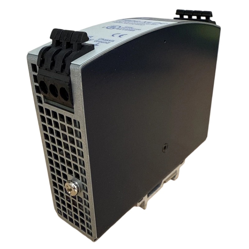
Allen Bradley 1606-XLDC92D Setup and Commissioning Validation
The Setup and Commissioning stage verifies whether the DC/DC Converter can support the actual automation system load.
Engineers should perform practical validation checks, including:
Measuring output voltage under normal load
Checking voltage recovery after load changes
Observing PLC Controller operation during startup
Confirming connected Modules remain stable
Verifying sensor signals remain consistent
A successful commissioning process should confirm that the converter works correctly in the real operating environment, not only during bench testing.
Allen Bradley 1606-XLDC92D System Configuration Verification
After installation, the converter should be reviewed as part of the complete automation power architecture.
The final System Configuration review should include:
Total connected device power consumption
PLC Controller expansion requirements
Module current demand
Sensor distribution layout
Possible future equipment additions
Many industrial power problems occur because additional devices are added after commissioning without recalculating the DC power capacity.
Long-tail Keywords for Allen Bradley 1606-XLDC92D Installation
This Installation Guide covers:
Allen Bradley 1606-XLDC92D DC/DC Converter installation
Allen Bradley 1606-XLDC92D wiring and commissioning
1606-XLDC92D Setup procedure for industrial automation
DC/DC Converter power system configuration
Allen Bradley PLC Controller power supply installation

