Allen-Bradley MPL-A430H-HJ72AA Servo Motor Installation Guide
Time:2026-09-01 Browse: 18
The Allen-Bradley MPL-A430H-HJ72AA is a low-inertia brushless AC servo motor designed for 230 V-class motion applications, with a 115 mm frame, 3500 RPM rated speed, keyed shaft, right-angle SpeedTEC DIN connector, and 2000-line incremental encoder. For a reliable installation, the important points are mechanical alignment, correct motor/feedback connections, and accurate servo drive configuration rather than simply applying motor power.
Allen-Bradley MPL-A430H-HJ72AA Servo Motor Installation Requirements
Before installation, verify the complete motor nameplate and confirm that the motor matches the selected servo drive and machine load.
The MPL-A430H-HJ72AA belongs to the MP-Series low-inertia servo motor family. It uses a 115 mm frame and 76.2 mm magnet stack, with a 3500 RPM rated speed and 2000-line incremental encoder. The motor has no factory-installed brake.
The official Rockwell Automation product information lists the motor as a 240 V AC rotary servo motor and identifies its current lifecycle status as discontinued, with MPL-A430H-SJ72AA listed as an engineering replacement. This is particularly important when preparing a new machine or replacing an existing motor.
MPL-A430H-HJ72AA Mechanical Installation and Alignment
The first practical check is shaft alignment.
Do not use the motor shaft to force a coupling into position. The coupling should slide into place without excessive radial or axial force. Misalignment can produce additional bearing loading, mechanical noise, position error, and unnecessary servo following error.
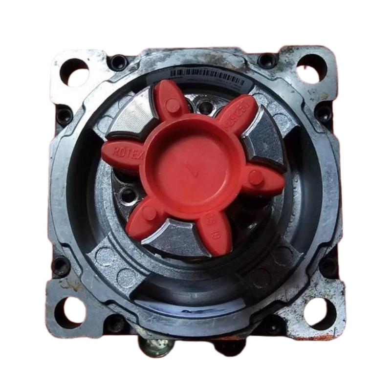
The motor uses an IEC metric mounting arrangement with free mounting holes. After mounting, rotate the mechanical assembly by hand where the machine design permits. A properly aligned system should turn smoothly without a noticeable tight spot.
For high-speed applications, the mounting surface should be rigid enough to prevent resonance. A motor that runs correctly without load can still generate excessive vibration after coupling to a flexible machine frame.
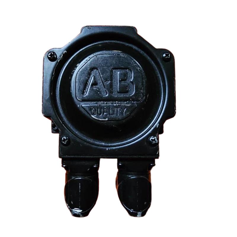
MPL-A430H-HJ72AA Motor and Encoder Connection Setup
Electrical installation should be treated as two separate functions: motor power and feedback.
The MPL-A430H-HJ72AA uses a right-angle SpeedTEC DIN connector that can be rotated for cable routing. The connector orientation is useful in compact cabinets, but the cable should still be routed with adequate separation from high-current switching conductors.
The incremental encoder is critical to closed-loop motion control. If the power connection is correct but the feedback connection is open, incorrectly wired, or electrically noisy, the drive may detect a feedback-related fault during enable or motion.
Before energizing the system, inspect connector seating, cable condition, shielding, and grounding. Do not assume that a motor that physically fits the machine is electrically compatible with the existing feedback cable.
Allen-Bradley MPL-A430H-HJ72AA Servo Drive Configuration
The servo drive must be configured for the exact motor catalog number or the appropriate motor data.
Where the drive supports direct motor selection, select MPL-A430H-HJ72AA rather than entering approximate motor values. This avoids incorrect current, feedback, and motor characteristic settings.
The motor is rated at 3500 RPM, while some published technical data also identifies a maximum operating speed of 5000 RPM. The machine's actual speed limit should therefore come from the complete drive and motor application requirements rather than from a single speed parameter.
System Configuration should also include the correct feedback type, motor direction, scaling, acceleration limits, and application-specific travel limits.
MPL-A430H-HJ72AA Commissioning and Rotation Check
Commissioning should begin at low mechanical risk.
With the machine secured and the load condition understood, enable the servo and command a small movement. Observe motor direction, feedback response, current behavior, and mechanical noise.
If the commanded positive direction produces negative physical movement, do not immediately modify random wiring. First check the axis direction configuration and mechanical coordinate definition.
A useful field practice is to commission the axis with progressively larger movements rather than immediately applying the full production motion profile.
During this check, listen for abnormal bearing noise and observe whether the motor accelerates smoothly. A low-inertia motor can respond quickly to command changes, so overly aggressive acceleration or gain settings may produce mechanical oscillation even when the wiring is correct.
Real Commissioning Case for MPL-A430H-HJ72AA
In one servo commissioning case, the motor powered up normally but produced a noticeable mechanical vibration during the first positioning test.
The initial assumption was that the motor or encoder might be defective. Instead of replacing the motor, the commissioning engineer reduced the acceleration and checked the coupling alignment. A small mechanical offset was found between the motor shaft and driven mechanism.
After correcting the alignment and repeating the low-speed test, the vibration was substantially reduced. The lesson is straightforward: when a servo motor passes electrical checks but behaves poorly under load, mechanical alignment should be investigated before declaring a motor failure.
Long-Tail Keywords for MPL-A430H-HJ72AA Installation
Common search terms associated with this installation include Allen-Bradley MPL-A430H-HJ72AA installation guide, MPL-A430H-HJ72AA servo motor setup, MPL-A430H-HJ72AA commissioning, Allen-Bradley MP-Series servo motor wiring, MPL-A430H-HJ72AA encoder connection, and MPL-A430H-HJ72AA servo drive configuration.
These terms describe practical commissioning tasks rather than separate product functions, and they are useful when troubleshooting an existing MP-Series motion axis.

