Woodward 8923-1262 Installation Kit Fault Diagnosis and Troubleshooting Guide
Time:2026-10-12 Browse: 0
Why Woodward 8923-1262 Installation Problems Need Systematic Diagnosis
Woodward 8923-1262 installation problems should be investigated by checking part compatibility, installation condition, and the host controller's diagnostic information before replacing control hardware. An alarm that appears after maintenance does not automatically indicate a defective PLC Controller, control module, or accessory.
The first diagnostic objective is to determine whether the fault originates from the installation kit, an incorrectly restored connection, an incompatible component, or an unrelated pre-existing system condition.
Recognizing Woodward 8923-1262 Installation Fault Symptoms
Installation-related problems can present differently depending on the kit's actual function and the equipment in which it is used. Relevant observations may include:
A component cannot be fitted into its intended position.
The supplied hardware does not match the approved parts list.
A controller alarm appears immediately after maintenance.
An existing control function changes following installation work.
The equipment fails a functional acceptance test despite appearing mechanically secure.
These symptoms are diagnostic clues, not proof of a particular failure. The controller's exact alarm text and the applicable product documentation should determine the next test.
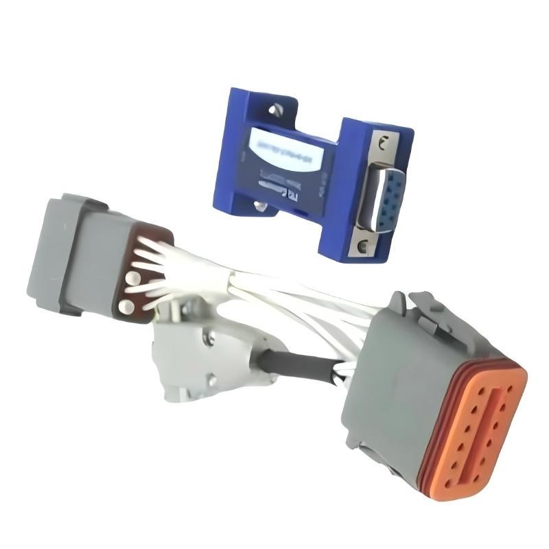
Woodward 8923-1262 Fault Diagnosis: Trace the First Abnormal Change
A useful troubleshooting approach begins with the maintenance timeline.
If the equipment operated normally before the installation and failed immediately afterward, inspect the work performed before investigating unrelated components. Review the removed parts, replacement part number, connection records, and any configuration changes made during the intervention.
If the fault was present before installation, do not attribute it to the 8923-1262 without additional evidence.
This distinction is especially important in generator-control systems, where an alarm may arise from an engine sensor, an interlock, a communication link, or a controller parameter rather than the accessory being installed.
A Representative Woodward 8923-1262 Troubleshooting Case
Consider a representative maintenance scenario in which a control system fails its acceptance test after an installation kit has been replaced.
The initial observation is that the system passed its previous operational checks but does not behave as expected after maintenance. Instead of immediately replacing the controller, the technician compares the new kit against the original parts list and checks whether the installation altered adjacent components.
The investigation proceeds through three questions:
Was the correct part installed? Verify the complete part number and the approved application.
Did the installation introduce a physical or connection problem? Inspect the affected area for loose hardware, disturbed wiring, obstructed movement, or incorrect component positioning, as applicable.
Does the host controller report a related fault? Compare the current diagnostic message with the recorded pre-maintenance condition and the controller manual.
If the discrepancy is traced to an incorrect component or an improperly restored connection, correct that issue and repeat the prescribed acceptance test. If the physical installation is correct but the fault persists, continue with the controller-specific diagnostic procedure.
This is an illustrative troubleshooting method, not a claim of a documented field repair for this particular part number.
Woodward 8923-1262 Troubleshooting: Measurements and Evidence
Measurements should be selected according to the confirmed function of the installed kit. Applying generic electrical tests to an unidentified accessory can produce misleading results or damage equipment.
For a verified electrical circuit, use the manufacturer's specified test points and acceptance limits. For a mechanical installation, check the approved dimensions, fastener requirements, and component alignment. For a controller-related alarm, capture the diagnostic code, operating state, and event sequence before resetting the fault.
For example, a measured supply voltage of 24 V DC is meaningful only when the applicable circuit is documented as a 24 V DC circuit and the measured value is assessed against its specified tolerance. It must not be assumed that the 8923-1262 itself requires that supply voltage.
A useful maintenance record includes the original symptom, verified part identity, test method, actual readings where applicable, corrective action, and final test result.
Restoring Woodward 8923-1262 System Operation
Once the root cause has been identified, correct the specific installation or configuration discrepancy rather than making unrelated parameter changes.
After correction, repeat the required mechanical inspection and functional checks. Confirm that the host controller has returned to its expected state, that the original control functions remain available, and that no new alarms have appeared.
If the fault persists, stop repeated replacement attempts and obtain the appropriate Woodward installation documentation or technical support. The exact kit function and compatible equipment must be established before recommending component-level repair.
Long-Tail Keywords for Woodward 8923-1262 Fault Diagnosis
This troubleshooting guide addresses common technical search queries, including Woodward 8923-1262 installation kit fault diagnosis, Woodward 8923-1262 compatibility checks, installation-related controller alarms, and Woodward accessory commissioning failures.
The central diagnostic principle is to verify the part, isolate the change introduced during maintenance, and use evidence from the actual controller and installation to identify the cause. This approach supports reliable Troubleshooting without treating an unverified symptom as proof of hardware failure.

