Schneider 140ACO13000C Analog Output Module Fault Diagnosis (Open-Loop Troubleshooting)
Time:2026-10-19 Browse: 1
Why Schneider 140ACO13000C Analog Output Channels Report Faults
A Schneider 140ACO13000C analog output module fault can result from an open 4–20 mA current loop, incorrect channel configuration, inadequate loop voltage, or a mismatch between the PLC output data and the field-device requirements. Because the Modicon Quantum module provides eight configurable current outputs, troubleshooting should begin with the affected channel rather than assuming that the complete module has failed.
The module supports open-circuit fault detection in 4–20 mA mode. Its local indicators include a green Active LED, a red external-fault LED, eight green channel-on LEDs, and eight red channel-fault LEDs. These indicators provide useful evidence, but the electrical signal and controller diagnostics must also be examined before deciding on a repair.
Interpreting Schneider 140ACO13000C Channel Fault Symptoms
The initial symptom helps determine which test should come next.
One channel reports a fault: Check the affected channel's wiring, receiving instrument, and output configuration first.
Several channels behave incorrectly: Review shared loop-supply conditions, common wiring, rack configuration, and controller diagnostics.
The PLC command changes but the field device does not respond: Compare the commanded value with the measured current at the output and receiving device.
The module remains active but one output is incorrect: Do not treat normal bus communication as proof that the individual output circuit is healthy.
These patterns narrow the investigation without prematurely identifying a failed component.
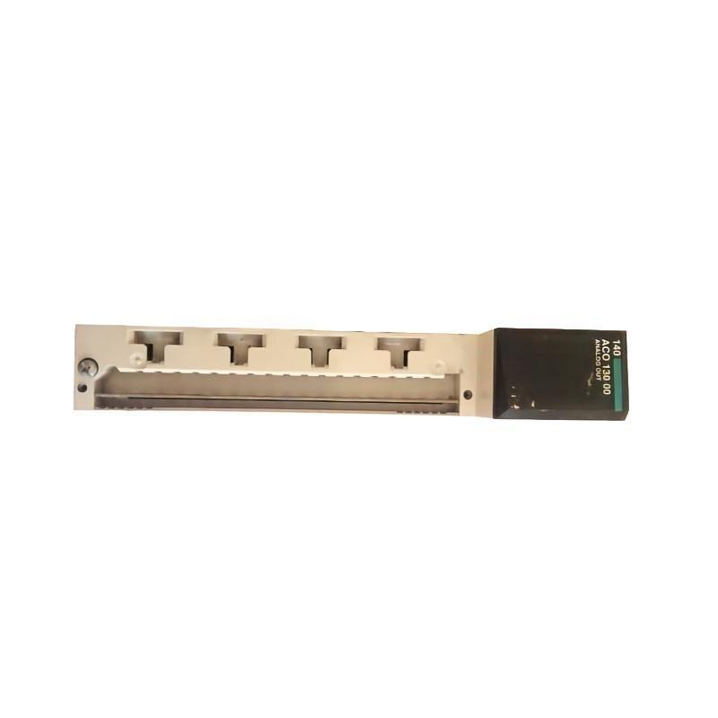
Schneider 140ACO13000C Fault Diagnosis: A Field-Based Investigation
Consider a representative plant scenario in which one control valve remains near its minimum position while the PLC program issues increasing output commands. The controller remains online, but the valve positioner reports a low current input.
The first task is to establish whether the command is changing as intended. Check the output variable, channel assignment, and scaling calculation. Next, inspect the channel fault indicator and measure the loop current using an approved procedure.
Suppose the project uses a linear 4–20 mA range with 0–16000 counts. A 75% command corresponds to approximately 12000 counts and a nominal current of 16 mA. If the PLC value reaches 12000 but the field current remains close to 4 mA, the discrepancy points toward a problem in signal generation, loop power, wiring, or output configuration.
The next measurement should distinguish the module output from the signal arriving at the positioner. A correct current at the module but an incorrect current at the receiving device directs attention toward the intervening circuit. An incorrect signal at the module requires further examination of the configuration, supply conditions, and module diagnostics.
This is an illustrative engineering scenario, not a verified repair history for a particular installation.
Checking External Loop Voltage and Wiring on the Schneider 140ACO13000C
The module specifies an external loop voltage of 6–30 V DC. Engineers should measure the available voltage under actual operating conditions and compare it with the requirements of the complete current loop.
Inspect the affected conductor, terminal connections, RETURN wiring, and field-device input terminals. Check for disconnected conductors, loose connections, damaged insulation, or incorrect termination.
When measuring current, use a suitable meter and the approved circuit-testing method. An ammeter must be inserted correctly into the circuit; connecting it directly across a voltage source can cause a short circuit. Isolate the circuit whenever required by the site's electrical safety procedure.
If an open-loop fault is indicated, restore the connection only after identifying the interruption and confirming the correct terminal assignments. Recheck the channel indicator and measure the current after the circuit has been restored.
Separating Schneider 140ACO13000C Scaling Errors from Hardware Faults
Not every output discrepancy originates in the analog hardware. The digital representation selected in the PLC project must agree with the output range configured for the channel.
For example, the 4–20 mA range can use either 0–4095 counts or 0–16000 counts. If a program uses a conversion intended for one representation while the project uses the other, the numerical output may be valid but the resulting current will not match the intended command.
A useful diagnostic comparison includes three values:
The commanded engineering value, such as 75%.
The raw output count written by the PLC program.
The measured current at the output circuit.
If the raw count does not match the expected scaling, correct the program or configuration according to the approved design. If the raw count is correct but the current remains incorrect, investigate the loop supply, wiring, channel diagnostics, and possible output-stage damage.
Hardware replacement becomes a reasonable consideration only after the external circuit and configuration have been verified.
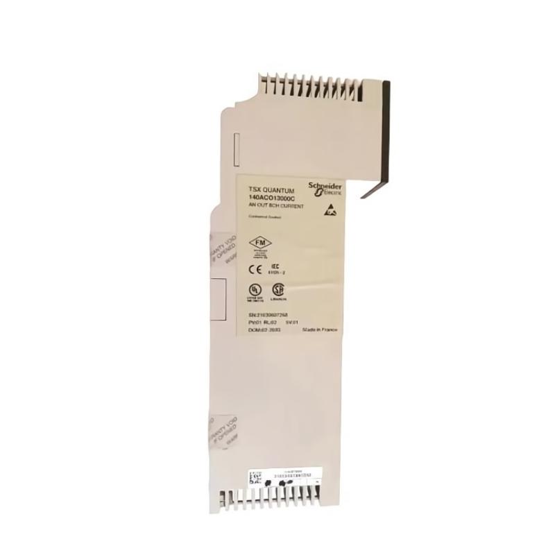
Schneider 140ACO13000C Repair Verification and Return to Service
Following a wiring or configuration correction, verify that the affected channel responds consistently at several safe test points. For a linear 4–20 mA range, nominal reference currents are 4 mA at 0%, 8 mA at 25%, 12 mA at 50%, 16 mA at 75%, and 20 mA at 100%.
Compare the measured values with the manufacturer's accuracy specifications and the requirements of the connected instrument. Confirm that the channel-fault indication has cleared where applicable and that the field device responds in the correct direction.
Document the original symptoms, diagnostic measurements, identified cause, corrective action, and final test results. If the output remains incorrect after wiring, loop supply, scaling, and controller configuration have been checked, follow the manufacturer's service procedure to determine whether the module requires further evaluation or replacement.
Schneider 140ACO13000C Troubleshooting: Long-Tail Fault Diagnosis Questions
For searches involving Schneider 140ACO13000C analog output troubleshooting, Modicon Quantum 4–20 mA open-circuit faults, and 140ACO13000C PLC output signal problems, the most reliable approach is to trace the signal from the software command to the physical load.
A successful repair must demonstrate more than a cleared alarm. The output command, configured current range, measured signal, and field-device response should all agree with the intended control strategy before the channel returns to normal operation.