Allen-Bradley MPL-B880C-SJ72AA Servo Motor Troubleshooting (Position Error Diagnosis)
Time:2026-10-20 Browse: 0
Diagnosing Position Errors on the Allen-Bradley MPL-B880C-SJ72AA Servo Motor
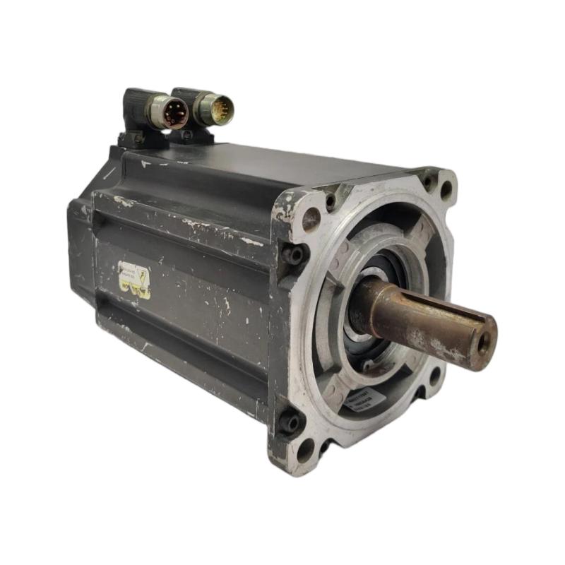
Allen-Bradley MPL-B880C-SJ72AA servo motor position errors are often associated with mechanical resistance, incorrect motion tuning, unstable encoder feedback, or a mismatch between the commanded and actual axis position. The motor is an MP-Series low-inertia brushless servo with a single-turn high-resolution encoder, making feedback integrity and correct motion configuration essential to accurate positioning. <Cite refs={["turn601994search0","turn601994search2"]}/>
A following-error alarm does not automatically mean the motor has failed. It indicates that the motion system has not maintained the expected relationship between commanded and actual position within the configured limits. The investigation must establish whether the discrepancy originates in the motor, feedback cable, drive, or connected mechanism.
Recognizing Allen-Bradley MPL-B880C-SJ72AA Position Fault Patterns
The timing of a position fault provides a useful starting point.
If the fault appears immediately when the axis is enabled, inspect motor identification, encoder feedback status, drive configuration, and the enable sequence. If the axis moves correctly at low speed but faults during acceleration, investigate load inertia, mechanical binding, and motion-profile settings.
Intermittent position errors that occur when nearby equipment switches may indicate electrical noise or a feedback-cable connection problem. Conversely, errors that repeatedly occur at the same mechanical position may point toward a tight coupling, damaged transmission component, or localized resistance.
Record the exact drive alarm, commanded position, actual position, motor current, and operating conditions before resetting the fault. These measurements are more useful than repeatedly clearing alarms without identifying their cause.
Allen-Bradley MPL-B880C-SJ72AA Troubleshooting Through Axis Data
Consider an illustrative machine scenario in which an axis operates normally at low speed but develops a following error when acceleration increases.
The first diagnostic question is whether motor current rises sharply at the same time as the position deviation. A sudden current increase accompanied by slowing motion may indicate excessive mechanical resistance or a load that exceeds the configured motion capability. If current remains relatively normal but actual position becomes unstable, inspect the feedback signal, tuning, and mechanical coupling.
For example, an engineer might observe that following error increases from 0.05 mm during low-speed travel to 0.40 mm during acceleration. These are hypothetical measurements, not published limits for the MPL-B880C-SJ72AA. Whether either value constitutes a fault depends on the machine's configured following-error threshold and required positioning accuracy.
The next step is to compare the same movement under controlled, reduced acceleration. If the error decreases substantially, investigate the load inertia, mechanical stiffness, and motion profile before increasing the following-error limit. If the error persists even at low speed, broaden the investigation to feedback integrity and mechanical alignment.
Encoder Feedback Fault Diagnosis for the MPL-B880C-SJ72AA
Because the MPL-B880C-SJ72AA uses a high-resolution single-turn encoder, incorrect or intermittent feedback can prevent the drive from determining motor position reliably.
Inspect the feedback connector and cable for loose connections, damaged insulation, contamination, or signs of mechanical strain. Verify cable compatibility and grounding against the applicable Rockwell Automation documentation. Separate feedback wiring from motor power conductors where required by the installation design.
Review the drive's feedback-related diagnostic information before replacing the motor. If the fault occurs intermittently, correlate the event with cable movement, machine vibration, and electrical switching activity. A fault that appears when a cable flexes may justify closer inspection of the connector or conductor continuity, provided testing is performed safely.
Do not open the motor or attempt an unauthorized encoder repair. If the feedback circuit and external cabling are verified but the encoder fault remains, follow the manufacturer's service procedure for further evaluation.
Mechanical Binding and Excessive Load on the Allen-Bradley MPL-B880C-SJ72AA
A servo axis can generate a following error even when its electrical components are functioning correctly. Excessive coupling misalignment, bearing damage, a tight ball screw, or an unexpected external load can prevent the motor from following the commanded trajectory.
With the machine safely isolated and stored mechanical energy controlled, inspect the coupling, mounting surfaces, transmission components, and driven mechanism. Check for signs of rubbing, unusual resistance, looseness, or damage. Never assume that a low-inertia motor can compensate for poor alignment or an unsuitable mechanical load.
The no-brake configuration of the MPL-B880C-SJ72AA also matters during maintenance. If the load can move when drive torque is removed, secure it using an appropriate mechanical restraint before disconnecting power or inspecting the transmission.
Once the mechanical condition has been verified, conduct a controlled motion test. Compare current demand, position deviation, and repeatability with the original observations to determine whether the suspected mechanical cause has been addressed.
Resolving MPL-B880C-SJ72AA Servo Tuning and Motion Profile Problems
If mechanical resistance and feedback faults have been excluded, examine the motion-control parameters. Excessive acceleration, abrupt deceleration, unsuitable loop gains, or an incorrect inertia estimate can cause oscillation and following-error faults.
Start with the approved machine configuration and compare it with the settings currently loaded in the drive. If the fault began after a parameter change, restore the last validated configuration where permitted by the site's change-control procedure.
Any tuning adjustment should be made incrementally and evaluated using actual position, velocity, current, and following-error trends. Avoid changing several parameters simultaneously, because doing so makes it difficult to identify the factor responsible for the improvement or deterioration.
A successful correction should reduce position deviation without introducing sustained oscillation, excessive current, or unacceptable settling time. Validate the result over the intended operating range before returning the axis to production.
Allen-Bradley MPL-B880C-SJ72AA Repair Verification and Fault Prevention
After corrective work, clear the fault only when the underlying condition has been addressed. Run the axis through a controlled sequence at low speed, then progressively increase acceleration within the approved operating limits.
Verify that the motor follows the commanded trajectory, the feedback remains stable, and the measured current is consistent with the mechanical load. Repeat representative movements to check positioning repeatability and confirm that the original fault does not recur.
The maintenance record should include the original alarm, the measured following error, the relevant current and position trends, the identified cause, and the corrective action. If the axis continues to fault after external wiring, configuration, tuning, and mechanical conditions have been verified, arrange qualified drive or motor service rather than assuming that the encoder or motor windings are defective.
Long-Tail Troubleshooting Guide for the Allen-Bradley MPL-B880C-SJ72AA
For Allen-Bradley MPL-B880C-SJ72AA servo motor troubleshooting, encoder feedback fault diagnosis, and following-error repair, the most effective approach is to distinguish symptoms from root causes.
Compare commanded motion with actual position, correlate the error with motor current and acceleration, and inspect the mechanical load before replacing hardware. This diagnostic sequence helps identify whether the problem lies in feedback, motion configuration, the drive, or the machine mechanics while reducing unnecessary component replacement.