Allen-Bradley MPL-B880C-SJ74AA Servo Motor Troubleshooting (Holding Brake Fault Diagnosis)
Time:2026-10-20 Browse: 1
Diagnosing Holding Brake Problems on the Allen-Bradley MPL-B880C-SJ74AA
Allen-Bradley MPL-B880C-SJ74AA servo motor brake faults can cause a stationary axis, unexpected motion during shutdown, or excessive motor current when motion is commanded. This MP-Series servo motor includes a 24 V DC holding brake and a single-turn high-resolution encoder. Troubleshooting must distinguish brake-circuit problems from drive-enable issues, mechanical resistance, and feedback faults.
The first question is whether the brake is failing to release, failing to hold the load, or operating correctly while another part of the motion system is preventing movement. These conditions can produce similar symptoms but require different diagnostic approaches.
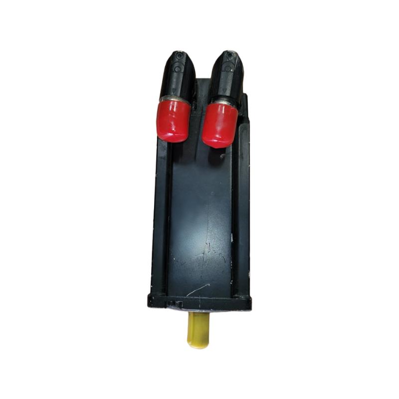
MPL-B880C-SJ74AA Servo Motor Symptoms and Initial Observations
When the motor does not rotate after a motion command, check the drive's enable status, active alarms, brake-control command, and feedback diagnostics before investigating the motor itself.
If the drive indicates that the axis is enabled but the motor remains stationary, a brake that has not released is one possible cause. If the motor moves normally but the load drifts after torque is removed, investigate the brake engagement sequence and the mechanical load-holding arrangement.
Excessive current during a movement command can indicate that the motor is attempting to move against a brake that remains engaged. Stop the test rather than repeatedly commanding motion, as continued operation under mechanical resistance may overheat the motor or damage the brake.
Record the alarm code, brake command state, measured supply voltage, motor current, and actual-position response before resetting the drive.
Fault Diagnosis: Checking the MPL-B880C-SJ74AA 24 V DC Brake Circuit
The SJ74AA brake requires a compatible 24 V DC control supply. A brake command shown in the PLC program does not prove that the brake is receiving the correct electrical supply or releasing mechanically.
Begin by reviewing the approved wiring diagram and confirming the brake-control output assignment. Check the supply and control-circuit status using suitable instruments and the site's electrical safety procedure.
If the brake does not release, investigate the following possibilities:
The brake-control output is not being activated.
The 24 V DC supply is missing or outside the specified operating conditions.
A cable, connector, or terminal connection is defective.
The configured release sequence does not match the drive's requirements.
The brake mechanism has developed an internal mechanical fault.
Use the exact motor and drive documentation to confirm connector pin assignments and electrical limits. Do not apply an unverified voltage directly to the brake terminals or bypass drive interlocks as a troubleshooting shortcut.
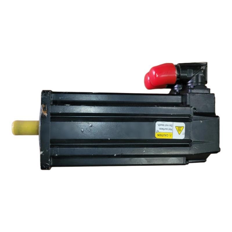
A Practical Investigation of an Axis That Will Not Move
Consider a representative packaging-machine axis that reports no major feedback fault but fails to move after an enable command. The drive displays an increasing current demand when a movement is attempted.
The initial evidence suggests mechanical resistance, but it does not establish the root cause. The engineer should first confirm whether the brake-release command is present and whether the electrical circuit responds as expected.
If the control command is absent, investigate the PLC sequence, drive configuration, and interlocks. If the command is present but the brake supply is incorrect, investigate the supply, wiring, and control output. If the electrical conditions are correct but the brake remains engaged, stop testing and arrange qualified inspection of the brake mechanism.
This example illustrates a fault-isolation process rather than a verified service event involving an individual MPL-B880C-SJ74AA motor.
Distinguishing Brake Faults from Encoder and Motion-Control Problems
Not every stationary-axis fault is caused by the holding brake. The motor's single-turn high-resolution encoder and servo drive must also provide valid feedback before normal motion can proceed.
Review the drive diagnostics for feedback faults, motor identification mismatches, and enable-sequence errors. If the brake is confirmed to release but the axis still does not move, inspect the commanded motion, actual-position data, current response, and mechanical transmission.
A feedback fault may prevent the drive from enabling the axis even when the brake circuit is healthy. Similarly, incorrect motion configuration or a mechanical obstruction can produce following-error alarms that resemble a motor failure.
Avoid changing multiple parameters at once. Confirm the cause through the available diagnostic evidence before adjusting tuning values or replacing components.
Troubleshooting an MPL-B880C-SJ74AA Brake That Does Not Hold
A different failure pattern occurs when the axis moves correctly during operation but the load shifts after the drive is disabled. In this case, the investigation should focus on brake engagement, the control sequence, mechanical loading, and the condition of the holding mechanism.
The motor's brake is a holding device, not a substitute for a properly engineered machine safety system. Gravity-loaded axes must be secured using the appropriate mechanical supports and safety procedures before maintenance or testing.
Verify that the drive follows the specified sequence for establishing torque, releasing the brake, stopping motion, and engaging the brake. Check whether the brake-control signal changes at the intended point in the sequence.
If the brake command and supply are correct but holding performance remains inadequate, take the axis out of service and follow the manufacturer's inspection and repair requirements. Do not compensate for a suspected brake defect by relying on increased servo torque or software settings alone.
Repair Verification and Return to Service for the MPL-B880C-SJ74AA
After a confirmed electrical or configuration fault has been corrected, repeat the relevant tests under controlled conditions. Verify that the brake releases when required, remains released during authorized motion, and engages according to the approved shutdown sequence.
Monitor motor current and following error during movement. For applications with vertical or suspended loads, use an approved test procedure that prevents uncontrolled descent and verifies the required holding performance.
Document the original symptoms, measured electrical values, diagnostic findings, corrective work, and final test results. If the brake still fails to operate correctly after the external circuit and configuration have been verified, obtain qualified service rather than attempting an undocumented internal repair.
Allen-Bradley MPL-B880C-SJ74AA Troubleshooting: Long-Tail Fault Diagnosis
For Allen-Bradley MPL-B880C-SJ74AA brake troubleshooting, 24 V DC holding brake fault diagnosis, and servo motor repair, the key is to separate electrical command problems from mechanical brake failure and unrelated drive faults.
A reliable diagnosis follows the evidence from the control sequence to the brake circuit, then to the motor feedback and mechanical system. Return the axis to service only after the brake behavior, motion performance, and required safety functions have been verified.