Woodward 9907-186 Load Distribution Module Installation Guide and Commissioning
Time:2026-10-22 Browse: 1
Woodward 9907-186 Load Distribution Module Installation Overview
The Woodward 9907-186 Load Distribution Module should be installed with particular attention to control-system compatibility, signal wiring, grounding, and load-sharing configuration. Incorrect connections or mismatched system settings can cause unstable load distribution, inconsistent generator loading, or unsuccessful commissioning. A reliable installation guide therefore starts with verifying the existing control architecture rather than connecting the module immediately.
The 9907-186 is identified as a Woodward load distribution module, with reported dimensions of 177 × 120 × 50 mm and a weight of 1.2 kg. Before installation, confirm these physical details against the actual unit and its applicable manufacturer documentation.
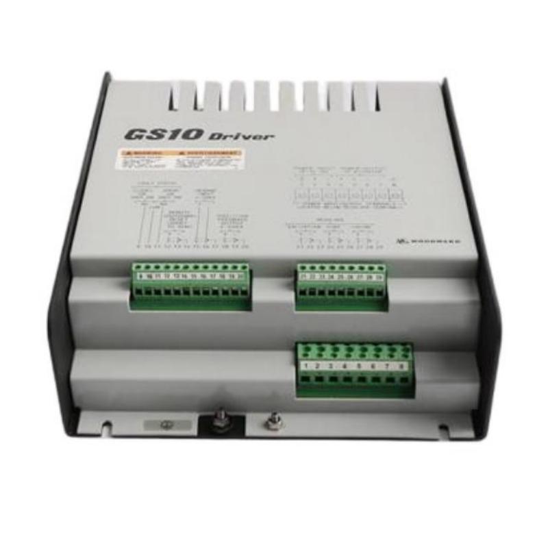
Woodward 9907-186 Module Function in a Generator Control System
In a generator control application, load distribution equipment helps coordinate how generating units share electrical demand. Depending on the system design, the module may form part of the signal path between generator controllers and the load-sharing network.
The precise function of the 9907-186 depends on its intended configuration and associated equipment. Engineers should verify the terminal assignments, supported signals, and operating requirements using the correct wiring diagram and technical manual.
A key commissioning distinction is that load sharing and synchronization are not the same function. A generator can synchronize successfully but still distribute real power unevenly after its breaker closes.
Woodward 9907-186 Installation Preparation and System Configuration
Before mounting the module, review the following items:
Equipment identification: Check the complete 9907-186 part number, hardware condition, and any revision markings.
System compatibility: Identify the connected generator controllers, governor equipment, and load-sharing interface.
Electrical requirements: Confirm the specified supply voltage, signal ranges, polarity, and terminal assignments from the applicable documentation.
Panel conditions: Check enclosure space, mounting security, ventilation, cable routing, and protection from vibration.
Safety arrangements: Apply the site's isolation and lockout procedures before handling wiring. Generator control circuits must be treated according to the installation's electrical safety requirements.
Record the existing wiring and parameter settings before modifying an operating system. This makes commissioning results easier to interpret and allows the original configuration to be restored if necessary.
Practical Wiring Checks for the Woodward 9907-186 Module
The installation should follow the manufacturer's terminal diagram rather than assumptions based on wire color or terminal position.
Separate low-level control signals from power conductors where the panel design permits. Verify cable continuity, shielding arrangements, and grounding practices against the system documentation. Incorrect polarity, an open signal conductor, or a poor common connection can create symptoms that resemble an internal module failure.
Where the module participates in a shared load-distribution signal path, also check the connections at the other participating controllers. A defect elsewhere in the network may affect the 9907-186 even when its own wiring appears correct.
Do not apply a supply voltage or connect an external test source until the relevant electrical specifications have been confirmed.
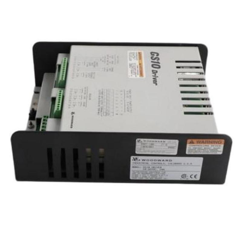
Woodward 9907-186 Setup and Commissioning Procedure
A controlled commissioning sequence reduces the risk of confusing wiring faults with configuration problems.
Initial verification: With the system safely isolated, inspect the mounting, terminals, cable routing, and protective earth arrangements required by the panel design.
Electrical verification: Compare the actual wiring against the approved diagram. Check the supply and relevant signal circuits using suitable test equipment and the manufacturer's specified measurement points.
Control-system review: Confirm that the connected controllers use compatible load-sharing arrangements and that their configuration agrees with the intended operating mode.
Functional testing: Perform the approved pre-start and operational checks. Where permitted by the commissioning procedure, observe the load-sharing response as generating units enter service and demand changes.
Acceptance recording: Document measured values, controller settings, test conditions, and any adjustments. Acceptance limits must come from the applicable equipment documentation and site procedures.
Woodward 9907-186 Load Sharing Validation During Startup
Consider a representative commissioning scenario in which two generators synchronize correctly, but one unit begins carrying noticeably more real power after the breakers close.
The engineer should not immediately replace the load distribution module. First, compare the generator kW readings with independent measurements, then inspect the load-sharing signal path, controller settings, and governor response. If the signal is consistent but the mechanical power response differs, the investigation should move toward governor calibration and control-loop behavior.
For example, if the measured outputs are 400 kW and 250 kW under a load-sharing condition where equal proportional loading is expected, the difference warrants investigation. Those figures are illustrative, not documented performance data for the 9907-186. Generator ratings, operating limits, and the configured sharing strategy must determine whether the observed difference is actually abnormal.
Woodward 9907-186 Installation Guide: Long-Tail Technical Checks
Engineers searching for a Woodward 9907-186 installation guide should prioritize these practical questions:
How can the 9907-186 load distribution module be integrated into an existing generator control system?
Which wiring and polarity checks should be completed before commissioning?
How can a load-sharing configuration problem be distinguished from a governor fault?
What measurements should be recorded during generator load-distribution testing?
How should the module be evaluated when generators synchronize but do not share load correctly?
The answers depend on the specific control-system design and manufacturer documentation. Avoid applying generic terminal assignments or parameter values from another Woodward module.
Woodward 9907-186 Installation Acceptance Criteria
The installation can be considered ready for operational handover only when the required electrical checks, control-system configuration reviews, and functional tests have passed the applicable acceptance criteria.
The final commissioning record should include the equipment identification, wiring verification results, relevant signal measurements, controller settings, operating conditions, and unresolved observations. This documentation provides a baseline for future Troubleshooting and Fault Diagnosis and helps maintenance personnel determine whether a later problem is new or existed during initial startup.