Woodward 9907-175A Load-Sharing Module Troubleshooting for PWM Signal Faults
Time:2026-10-22 Browse: 1
Woodward 9907-175A PWM Output Fault Diagnosis
A suspected PWM output fault in a Woodward 9907-175A Load-Sharing Module should be investigated by separating the module's output behavior from the receiving engine controller's response. If a generator fails to increase or decrease its real-power output as expected, the problem may involve the PWM signal, the wiring interface, controller compatibility, or the engine speed-control system.
An important identification check comes first: Woodward Manual 02036 documents the PWM-output Load Sharing Module models 9907-175 and 9907-838. The exact 9907-175A suffix should be verified against the unit label and applicable documentation before using model-specific wiring or test values. The published 9907-175 manual provides a useful diagnostic reference, but its specifications should not automatically be assigned to a differently identified unit.
Woodward 9907-175A Load-Sharing Module: Recognizing a PWM Control Fault
A PWM-related fault may present in several ways:
Generator loading does not respond correctly to the load-sharing controller.
One generator carries a disproportionate share of the parallel load.
Engine speed or real-power output changes unexpectedly after a load-sharing command.
The receiving engine controller does not respond consistently to changes in the control signal.
The load-sharing system operates correctly under some conditions but becomes unstable as demand changes.
These symptoms do not establish that the module itself has failed. The diagnostic objective is to determine whether the expected control signal is generated, transmitted, and interpreted correctly.
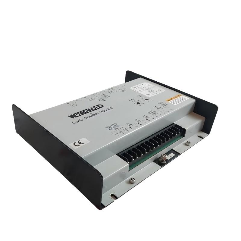
Woodward 9907-175A Troubleshooting: Follow the PWM Signal Path
A useful fault-isolation strategy begins at the receiving controller and works backward toward the module.
Receiving controller: Confirm that the engine speed-control equipment is compatible with the documented PWM output interface. Check the configured input type, wiring reference, and permitted signal range.
Interconnecting wiring: Inspect the cable, terminal connections, and signal return path. A loose terminal or poor electrical connection can produce an intermittent response that resembles an internal output fault.
Module output: Measure the signal only at documented test points, using an instrument and procedure suitable for the circuit. Compare the observed waveform and operating response with the specifications applicable to the confirmed model.
Engine response: If the PWM signal behaves as specified but engine output does not follow the command, investigate the receiving controller, governor, actuator, and engine operating condition.
This sequence helps distinguish an electrical interface problem from a control or mechanical problem without replacing parts unnecessarily.
Woodward 9907-175A Fault Diagnosis Using Signal Measurements
For the documented 9907-175 PWM-output module family, Manual 02036 specifies a PWM frequency of 500 ± 100 Hz. It also describes duty-cycle variation as the load-sharing controller adjusts its command. These values are relevant to the documented 9907-175 design and should be applied to a unit marked 9907-175A only after confirming that the same specification applies to its revision.
During troubleshooting, record the following observations:
| Diagnostic measurement | What the result helps establish |
|---|---|
| Module supply voltage | Whether the supply meets the applicable specification |
| PWM frequency | Whether the output frequency is within the documented range |
| PWM duty cycle | Whether the control command changes as expected |
| Signal at the receiving controller | Whether the signal reaches the destination correctly |
| Engine power response | Whether the governor and engine respond to the command |
Do not interpret a frequency measurement alone as proof of correct operation. A signal may have the expected frequency but an incorrect duty cycle, unstable waveform, or inadequate electrical interface for the receiving controller.
Woodward 9907-175A Case Analysis: Signal Present but Load Response Incorrect
Consider a representative generator-maintenance scenario in which the engine runs normally, but its real-power output does not follow the expected load-sharing command.
The engineer first verifies the actual kW reading and checks whether the load-sharing command changes with demand. The PWM output is then compared with the applicable specification, followed by a measurement at the receiving controller.
If the signal is correct at the module but incorrect at the controller, the investigation should focus on the interconnecting wiring and interface. If the signal reaches the controller correctly but the engine does not respond, the next checks should involve the controller configuration and governor response.
If the signal itself fails to follow the expected command despite verified supply, wiring, and operating conditions, the module becomes a stronger suspect.
The readings in this scenario are intentionally qualitative; they are not presented as a verified field repair or actual test record for a 9907-175A unit.
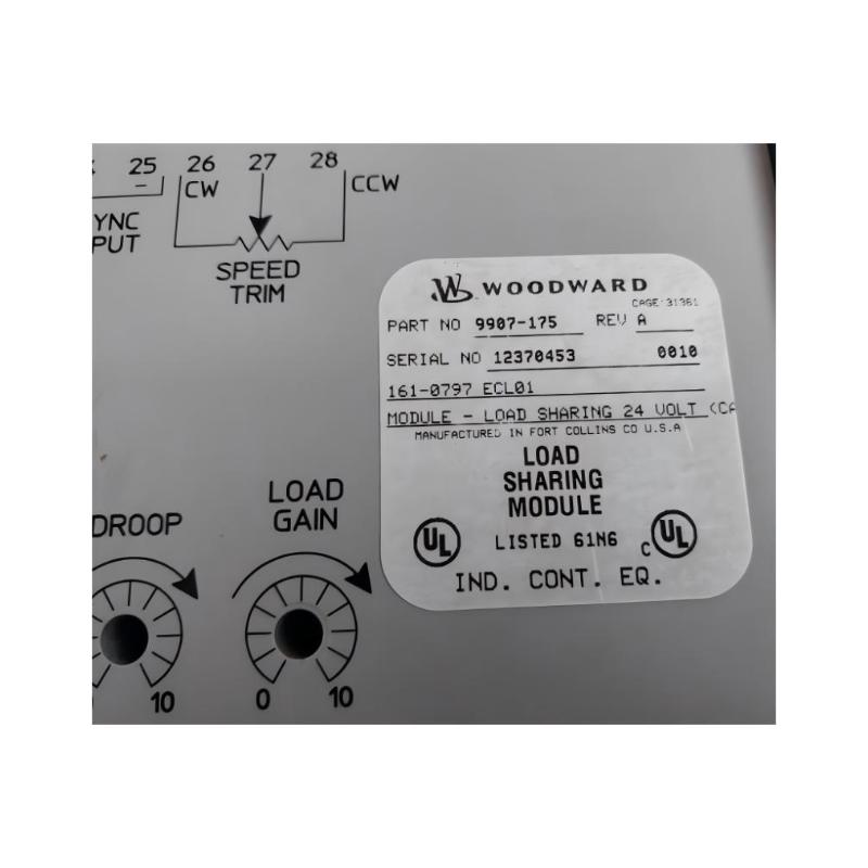
Woodward 9907-175A Troubleshooting for Unequal Generator Loading
PWM faults are only one possible explanation for uneven load sharing. The Woodward load-sharing system documentation also identifies other potential causes, including unequal load-gain settings, incorrect current-transformer phasing, and problems involving droop or isochronous operating mode. These alternatives should be evaluated where applicable to the confirmed module and generator-control configuration.
For example, if the PWM output responds correctly but two generators continue to carry different proportions of real power, check the load-sharing configuration and relevant current-sensing circuits before concluding that the output stage is defective.
Where generators exhibit unequal power factors or circulating reactive currents, investigate generator voltage-regulator behavior separately. Real-power load sharing and reactive-power sharing involve different control functions, and correcting one does not necessarily correct the other.
Woodward 9907-175A Module Repair and Recovery Decisions
Repair or replacement should follow a verified diagnosis rather than a single abnormal operating symptom.
Incorrect signal at the module: Confirm the supply, operating conditions, and applicable test procedure before considering an internal fault.
Correct module output but incorrect signal at the controller: Inspect the interconnecting wiring and electrical interface.
Correct signal at the controller but incorrect engine response: Investigate controller settings, governor operation, and the engine control chain.
Correct PWM behavior but unequal generator loading: Examine load-sharing configuration, current sensing, and other relevant control-system functions.
Before changing settings, record the original configuration. Follow the manufacturer's restrictions on servicing electronic assemblies; internal repairs should be performed only within the approved service scope.
Woodward 9907-175A Fault Diagnosis and Post-Repair Validation
After corrective action, repeat the relevant electrical and functional checks under controlled operating conditions. Verify that the PWM signal remains within the applicable specifications and that the receiving controller responds consistently as the load changes.
Where parallel operation is involved, confirm that the generators share real power according to their ratings and the configured operating strategy. Record the initial symptom, measurements, root cause, corrective action, and post-repair results.
For maintenance teams, this evidence-based Troubleshooting process provides a more reliable basis for determining whether a Woodward 9907-175A Load-Sharing Module requires replacement or whether the fault lies elsewhere in the System Configuration.