Allen-Bradley 100S-D210EA22BC Safety Contactor Troubleshooting for Welded Contacts
Time:2026-10-23 Browse: 0
Allen-Bradley 100S-D210EA22BC Safety Contactor Failure Symptoms
When an Allen-Bradley 100S-D210EA22BC Safety Contactor fails to disconnect a motor circuit after an emergency-stop command, welded main contacts must be considered alongside control-wiring and mechanical faults. A contactor coil can de-energize correctly while a damaged main contact remains electrically closed, creating a potentially hazardous condition.
The 100S-D family uses mirror-contact functionality to support external safety monitoring. However, diagnosis must distinguish the actual state of the main power contacts from the control command and auxiliary feedback indication. A PLC status bit alone is not sufficient evidence that hazardous power has been isolated.
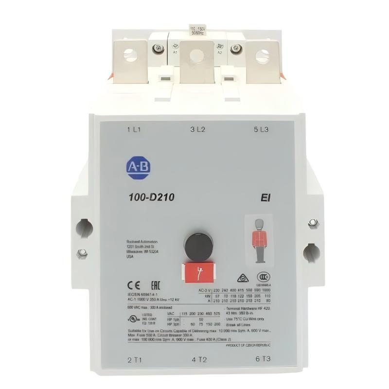
Allen-Bradley 100S-D210EA22BC Troubleshooting: When the Motor Does Not Stop
Consider a representative fault scenario on a production conveyor. The operator presses the emergency-stop button, the safety controller removes the contactor command, but the motor continues to receive power.
The initial observation creates three diagnostic questions:
Did the contactor coil actually lose its control supply?
Did the main contacts physically open?
Did the safety feedback circuit correctly report the contactor's state?
These questions separate an electrical control fault from a potential contactor failure. The investigation should begin by placing the machine in a safe condition and preventing unexpected restart. If hazardous power remains present, follow the site's emergency isolation procedure rather than repeatedly operating the contactor.
Allen-Bradley 100S-D210EA22BC Fault Diagnosis: Establishing the Actual Contact State
A structured Fault Diagnosis process should compare the commanded state with the observed electrical and mechanical behavior.
Control command: Review the safety controller's output status and determine whether the contactor command was removed during the stop request.
Coil circuit: A qualified technician should verify the coil supply using the approved test procedure. If the coil remains energized, investigate the output circuit, wiring, and control-device behavior before attributing the fault to welded contacts.
Main power circuit: If the coil has de-energized but the load remains powered, the contactor's main contacts may have failed to open. Isolate all relevant energy sources before conducting continuity or resistance tests.
Safety feedback: Check whether the designated mirror contacts report the expected state. A mismatch between the main contacts and feedback circuit requires investigation; the feedback signal should not be treated as a substitute for verifying electrical isolation.
Allen-Bradley 100S-D210EA22BC Main Contact Welding: Likely Causes
Main contact welding can result from electrical and mechanical stress. The likely causes depend on the motor, switching duty, and protective-device arrangement.
Excessive starting current: Frequent motor starts or high inrush current can increase contact stress when the contactor is not properly selected for the actual duty.
Unsuitable utilization category: A contactor selected without considering the application's starting, stopping, reversing, or plugging duty may experience more severe switching stress than expected.
Short-circuit or overload events: Abnormal current conditions can damage switching contacts. Check the protective-device coordination and investigate the original event before returning the equipment to operation.
Mechanical deterioration: Wear, contamination, or damage to the operating mechanism can affect contact movement and reliable opening.
Incorrect application or installation: Inadequate terminal connections, inappropriate accessories, or operation outside the specified conditions may contribute to overheating or premature failure.
These are potential causes rather than confirmed failure characteristics unique to the 100S-D210EA22BC.
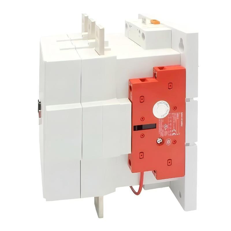
Allen-Bradley 100S-D210EA22BC Troubleshooting with Electrical Measurements
Measurements should be selected according to the fault, the approved circuit diagram, and the manufacturer's service instructions.
| Test item | Diagnostic purpose |
|---|---|
| Coil supply during the stop command | Establish whether the coil circuit de-energizes |
| Load-side voltage under an approved test procedure | Determine whether hazardous voltage remains present |
| Main-contact continuity after verified isolation | Check whether a power pole remains closed |
| Auxiliary mirror-contact state | Verify the monitored contactor state |
| Motor starting and operating current records | Investigate abnormal electrical stress |
| Protective-device trip history | Identify possible overload or short-circuit events |
Do not perform live measurements or resistance tests without the appropriate qualification, isolation, and test procedure. Never rely solely on an indicator lamp or PLC input to establish that a power circuit is safe.
Allen-Bradley 100S-D210EA22BC Repair Strategy and Corrective Action
If welded main contacts are confirmed, remove the contactor from service and replace or service it according to the manufacturer's approved procedures. Do not attempt to restore a safety contactor by manually separating welded contacts or by bypassing the feedback circuit.
Before installing a replacement, investigate why the original device failed. Confirm that the contactor is correctly rated for the motor and switching duty, check protective-device coordination, and inspect the power terminals and surrounding wiring for thermal damage.
If the contactor opens correctly but the feedback signal remains incorrect, investigate the auxiliary-contact circuit and safety-controller input configuration. Replacing the entire contactor without confirming the fault may not resolve a wiring or monitoring problem.
Allen-Bradley 100S-D210EA22BC Post-Repair Safety Validation
Following replacement or approved repair, validate the complete safety function rather than testing the contactor in isolation.
The validation should confirm that:
The contactor operates consistently under its specified control conditions.
The monitored feedback contacts provide the expected state information.
An emergency-stop demand produces the intended safety response.
The system detects relevant contactor-state discrepancies according to its safety design.
Unexpected restart is prevented where required by the validated safety architecture.
Record the original failure, measured evidence, identified cause, corrective action, and final test results. If the original event involved excessive current, overheating, or a protective-device operation, document the investigation and corrective measures before resuming production.
Allen-Bradley 100S-D210EA22BC Troubleshooting: Preventing Repeat Failures
Preventive maintenance should focus on the actual operating conditions rather than replacement intervals alone. Review switching frequency, motor starting characteristics, protective-device coordination, terminal condition, and safety-feedback performance.
Recurring welded-contact faults indicate that the underlying electrical stress or application problem may remain unresolved. Similarly, repeated feedback discrepancies require examination of the monitoring circuit instead of simply resetting the safety controller.
For the Allen-Bradley 100S-D210EA22BC Safety Contactor, effective Troubleshooting combines electrical measurements, control-system analysis, and functional safety validation. A verified root cause and documented post-repair test provide a stronger basis for reliable operation than replacing hardware based on symptoms alone.