Allen Bradley 20BD022A0AYNANC0 PowerFlex 700 AC Drive Installation and Commissioning Guide
Time:2026-10-26 Browse: 1
PowerFlex 700 AC Drive Installation Planning and Electrical Compatibility
The Allen Bradley 20BD022A0AYNANC0 PowerFlex 700 AC Drive requires a compatible 480 VAC three-phase supply, correctly rated motor wiring, and verified control parameters before commissioning. With a nominal output current rating of 22 A, this variable frequency drive is intended for applications requiring controlled AC motor speed and torque. Its catalog configuration includes 24 V DC control I/O, vector control, an internal braking IGBT, and no factory-installed communication module.
The first installation decision is whether the existing electrical system matches the drive's actual configuration. A matching PowerFlex 700 family designation does not guarantee identical I/O voltage, feedback hardware, or communication options across different catalog numbers.
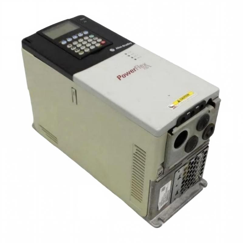
Preparing the 20BD022A0AYNANC0 Drive for Panel Installation
Before installation, verify the complete catalog number and hardware series against the nameplate and the applicable Rockwell Automation documentation. The model is rated for 480 VAC three-phase input, with a normal-duty rating of 15 HP and a heavy-duty rating of 10 HP. Confirm the intended duty rating against the machine's actual load requirements rather than selecting the drive based on horsepower alone.
The enclosure is IP20 / NEMA Type 1, with conformal coating. Consequently, the drive must be installed in an environment consistent with its protection rating, contamination limits, and cooling requirements.
Inspect the panel for sufficient clearance, unobstructed airflow, and separation between power and low-level control wiring. Verify that the branch-circuit protective devices, disconnecting equipment, conductors, and grounding arrangement comply with the applicable installation instructions and electrical codes.
PowerFlex 700 Power Wiring and Noise-Control Considerations
A sound installation separates the incoming supply circuit from the motor output circuit and control wiring. Connect the incoming three-phase supply and motor conductors to the terminals identified in the model-specific installation manual. Connect protective earth according to the manufacturer's grounding instructions.
The 20BD022A0AYNANC0 includes an EMC filter and common-mode choke configuration. These features do not eliminate the need for correct cable routing, shield termination, and grounding. Poor installation practices can still produce electrical interference in analog feedback, digital inputs, and nearby PLC equipment.
Before energizing the drive, inspect the following:
Confirm that input voltage and phase configuration are correct.
Check motor conductor routing, terminal identification, and protective earth continuity.
Verify that motor insulation and cable condition meet the approved test procedure.
Confirm that external run commands cannot unexpectedly start the machine.
Ensure that all wiring and covers are secured before power is restored.
Never interchange input and output terminals. Before accessing internal components, isolate all energy sources, observe the specified DC bus discharge period, and verify the absence of hazardous voltage with a suitable instrument.
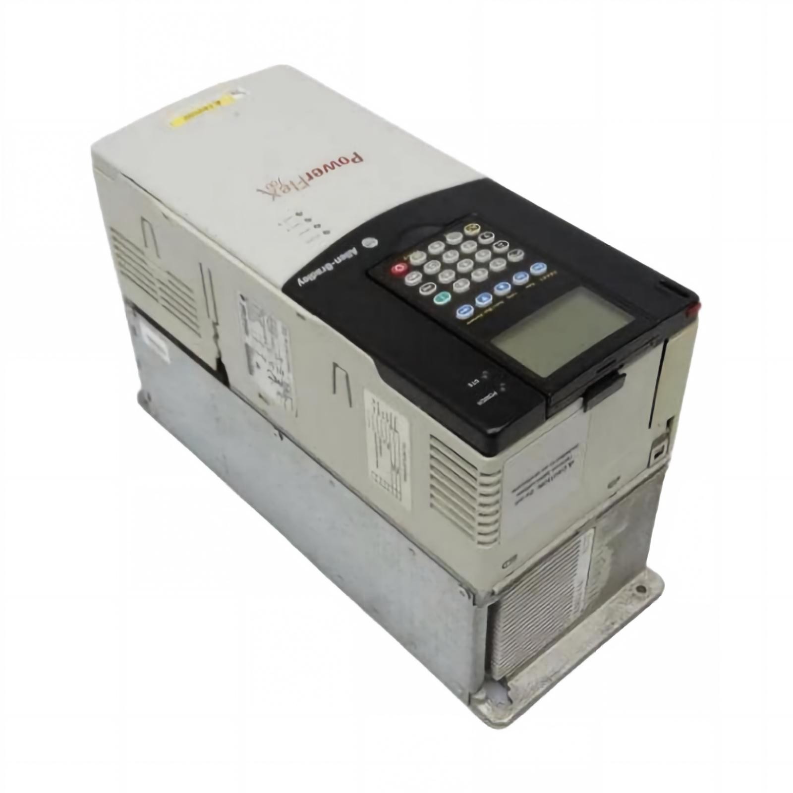
Motor Parameter Setup for 20BD022A0AYNANC0 Commissioning
The PowerFlex 700 Setup / Commissioning process begins with entering the motor nameplate information into the drive's supported parameter interface. Configure rated voltage, current, frequency, speed, and other required values according to the motor and selected control mode.
The drive's catalog configuration specifies a blank operator-interface cover rather than an installed Human Interface Module (HIM). Therefore, confirm the available parameter-access method and any required accessories before scheduling commissioning. Do not assume that a keypad is included with the drive.
Acceleration and deceleration settings should reflect the machine's inertia and operating cycle. For example, a loaded conveyor may require a longer acceleration ramp than a lightly loaded fan. Where braking is necessary, remember that the installed braking IGBT does not mean a braking resistor is included. Any external braking arrangement must be selected and installed in accordance with the manufacturer's specifications.
PLC Controller Integration and System Configuration Verification
When the 20BD022A0AYNANC0 is controlled by a PLC Controller, the commissioning engineer must verify both the drive parameters and the control interface. This model is specified with 24 V DC I/O and no internal communication module, so the actual command method must be established from the project drawings and installed hardware.
For hardwired control, verify the control supply, input assignments, common reference, and start/stop logic. For network control, confirm that the appropriate compatible communication hardware has been installed and configured.
A useful commissioning test compares three signals: the PLC's requested run command, the drive's recognized command, and the drive's reported operating status. If the PLC output changes but the drive does not respond, investigate the interface and System Configuration before concluding that the drive's power section has failed.
Field Validation of PowerFlex 700 Installation Quality
Consider a representative commissioning scenario in which the drive powers up normally but the connected motor does not rotate. The initial observation alone does not identify a hardware failure. The engineer should first check the displayed fault status, command source selection, control-input states, and motor parameter configuration.
If the run command is absent at the drive, attention should shift to the PLC output, terminal wiring, or control logic. If the command is recognized but a fault occurs during acceleration, investigate the recorded fault code, motor current, load condition, and ramp settings.
These are diagnostic examples rather than documented results from a specific installation. Actual acceptance criteria must be based on the equipment ratings, manufacturer instructions, and machine requirements.
Before releasing the machine, test motor rotation, low-speed operation where appropriate, normal stopping, interlocks, and representative loading. Record the final parameter values and test observations so that future Troubleshooting can be based on a verified baseline.
Long-Tail Search Terms for Allen Bradley 20BD022A0AYNANC0
This Installation Guide addresses Allen Bradley 20BD022A0AYNANC0 installation, PowerFlex 700 AC Drive wiring, 480 V variable frequency drive commissioning, PowerFlex 700 motor parameter setup, 24 V DC drive control wiring, PLC Controller integration, and PowerFlex 700 System Configuration verification. Use the exact catalog-number documentation to confirm terminal assignments, electrical limits, and approved commissioning procedures.