Schneider ATV610 VFD Troubleshooting Guide: Practical Diagnostics Methods to Improve Maintenance Eff
Time:2026-06-17 Browse: 10
Meta Description:
A practical troubleshooting and inspection guide for Schneider Electric ATV610 variable frequency drives, covering fault codes, safety checks, IGBT testing, DC bus diagnostics, and preventive maintenance strategies for industrial applications.
Schneider ATV610 VFD Troubleshooting Guide: Practical Diagnostics Methods to Improve Maintenance Efficiency
The Schneider ATV610 series is widely used in variable torque applications such as fans, pumps, HVAC systems, and water treatment facilities. With a power range from 0.75 kW up to 800 kW, it has become a common industrial drive in manufacturing and infrastructure systems.
However, long-term operation inevitably leads to faults such as overcurrent trips, overheating alarms, undervoltage errors, and unexplained fault codes. Efficient troubleshooting is therefore critical to minimizing downtime and maintenance costs.
This guide provides a practical field-oriented diagnostic approach for ATV610 drives, focusing on safety procedures, fault code interpretation, electrical testing methods, and preventive maintenance.
1. Safety Procedures Before Inspection
Before performing any inspection on the ATV610 drive, strict safety measures must be followed:
Disconnect main power supply completely
Remove plug or isolator connection
Ensure grounding is safely disconnected
Wait at least 30 minutes for internal capacitors to discharge
Even after waiting, residual DC voltage may remain in the DC bus capacitors. Use a discharge resistor tool (typically ≤10Ω) to safely discharge the DC bus.
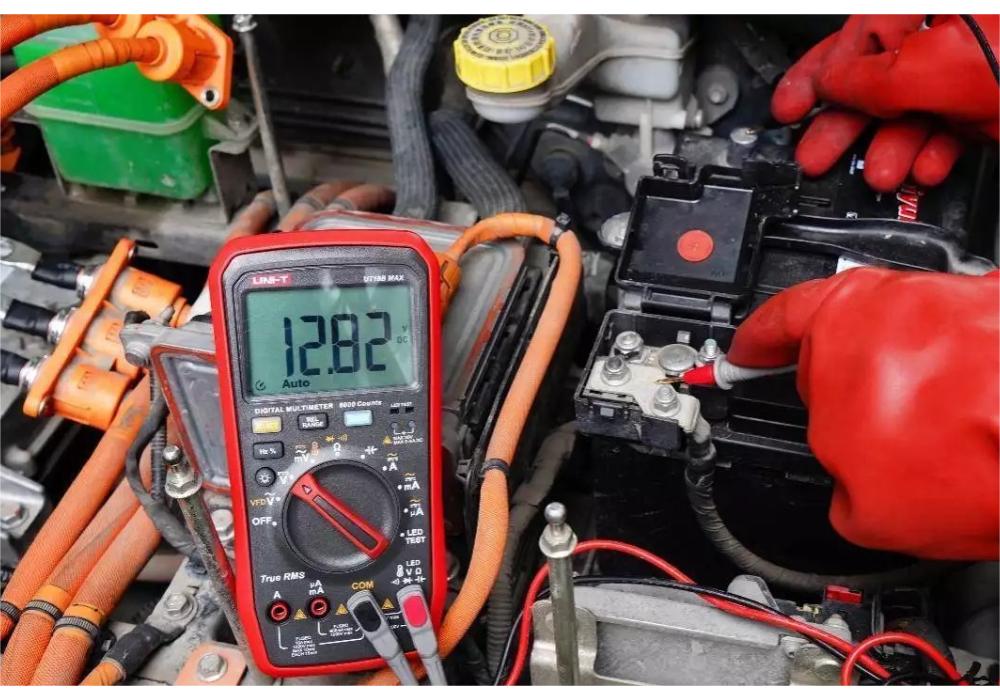
Finally, verify with a digital multimeter (DC 1000V range) that voltage between PA/+ and PC/- terminals is below 50V before touching internal components.
Recommended tools include:
Digital multimeter
500V/1000V insulation tester (megohmmeter)
Infrared thermal camera or thermometer
Oscilloscope
Clamp meter
Environmental conditions should also be checked:
Input voltage fluctuation within ±10%
Harmonic distortion (THD) below 5%
Minimum 30 cm ventilation clearance
Separation of power and signal cables with shielded twisted pairs where required
2. Fault Code Interpretation for Faster Diagnosis
Understanding fault codes is essential for rapid troubleshooting:
OCF (Overcurrent): Often caused by too short acceleration time or sudden mechanical load blockage
OUF (Overvoltage): Typically related to fast deceleration or failed braking resistor
OHF (Overheat): Check cooling fan operation and heat sink cleanliness
USF (Undervoltage): Inspect input power supply and fuse condition
INFP Internal Fault 25: Often linked to hardware and firmware mismatch; requires manufacturer support
Correct interpretation helps reduce unnecessary component replacement and downtime.
3. Three-Stage Field Diagnostic Method
A structured “three-stage approach” improves troubleshooting efficiency:
Stage 1: Power Section Check
Measure three-phase input voltage balance (deviation ≤ ±3%)
Check DC bus voltage (typically 500–540V for 380V systems)
Monitor module temperature (attention required above 60°C)
Stage 2: Control Circuit Inspection
Verify CN01 terminal signal integrity
Check encoder shielding and grounding quality
Confirm PG card LED status and signal response
Stage 3: HMI and Interface Check
Confirm keypad responsiveness
Check display clarity and alarm readability
Verify communication and parameter access
4. Common Maintenance Mistakes to Avoid
Field technicians often encounter preventable errors:
Working on live circuits without proper discharge verification
Using standard multimeters to test insulation resistance (insufficient voltage output)
Misdiagnosing fault codes and replacing entire units unnecessarily
Ignoring minor contact issues causing intermittent SCF3-type faults
For insulation testing, a megohmmeter must be used. Motor insulation resistance should generally not be lower than 10 MΩ.
5. Heat Dissipation and Mechanical Inspection
Thermal management is critical for drive reliability:
Clean heat sink when dust exceeds 2 mm thickness
Use dry compressed air (<0.4 MPa) for cleaning
Avoid water or chemical solvents
Ensure encoder radial runout is within 0.1 mm
Incorrect encoder installation or excessive vibration often leads to unstable speed control.
6. Key Electrical Testing Points
DC Bus Voltage
Normal range: ~500–540V (for 380V input systems)
Low or zero voltage: possible rectifier or pre-charge circuit failure
Excessively high voltage (>1000V): check grid and braking system
IGBT Module Testing
Diode test forward drop: ~0.3–0.5V
Short or open circuit indicates module failure
Braking Resistor Check
Resistance deviation: within ±5%
Surface temperature: below 80°C during operation
No cracking or bulging allowed
7. Parameter Adjustment Recommendations
For stable operation:
Acceleration/deceleration time ≥ 3 seconds
Carrier frequency: ~6 kHz (low power), reduced for high power
Motor rated current parameter: set ~30% above nameplate value
PID control for pumps/fans: use AI2 4–20 mA feedback
Increase proportional gain gradually; avoid overly short integral time
Always back up parameters before modification to avoid configuration loss.
8. Preventive Maintenance Strategy
A structured maintenance cycle improves equipment lifespan:
Daily: temperature and ventilation check
Weekly: terminal tightening
Monthly: insulation resistance measurement
Quarterly: cleaning and fan inspection
Semi-annual: keypad and terminal oxidation check
Annual: capacitor and braking resistor inspection
Recommended replacement cycle:
Electrolytic capacitors: ~3 years
IGBT modules: based on waveform distortion (>10%)
With proper maintenance, ATV610 drives can reliably operate for 8–10 years in industrial environments.
Conclusion
Efficient troubleshooting of ATV610 drives requires a combination of safety discipline, structured diagnostics, and correct interpretation of fault signals. By following standardized inspection procedures and preventive maintenance schedules, industrial users can significantly reduce downtime and improve system reliability in demanding applications such as HVAC, water treatment, and manufacturing automation.

