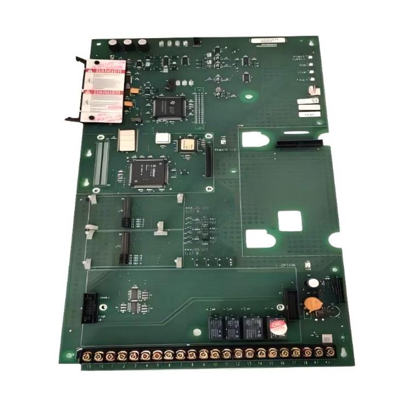
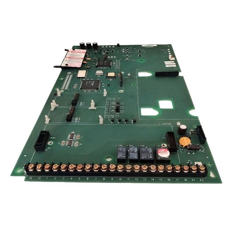
Allen-Bradley 1336F-MCB-SP1F Control Board Communication Fault Troubleshooting Guide
Time:2026-06-17 Browse: 7
Allen-Bradley 1336F-MCB-SP1F control board communication faults are frequently misinterpreted as inverter failure, but in most real-world cases the root cause is intermittent enable loop instability, TB3 signal noise, or degraded J2 backplane connection, not full board destruction.
In one industrial packaging line, the drive tripped randomly every 20–40 minutes under constant load. Replacement of the control board did not solve the issue. The real root cause was found in a loose TB3 enable circuit terminal with intermittent 24V dropout.
<h2>1336F-MCB-SP1F PLC Control Board Fault Symptoms in 1336 Drive Systems</h2>
Typical symptoms observed in field failures include:
HIM display freezes during operation
Random “Enable Fault” without load change
Drive resets after vibration impact
Communication loss between control board and adapter module
Fault buffer shows intermittent CP/VP mismatch events
In unstable cases, the drive may still run at low speed but trip above 40–50Hz due to timing drift in velocity processor synchronization.
<h2>1336F-MCB-SP1F Intermittent Enable Fault Root Cause Analysis</h2>
In a real diagnostic case on a pump station VFD, engineers observed:
Motor current stable at 18–22A
No mechanical overload
Fault occurred only during high humidity periods
After inspection, the root cause was identified as:
Oxidized TB3 terminal connection
Slight voltage drop from 24V enable line (down to 18.6V)
Resulting in unstable logic level detection on control board
The control board interpreted this as an intermittent enable interlock open condition, triggering shutdown.
<h2>1336F-MCB-SP1F Communication Drop Fault Diagnosis Logic</h2>
When communication failure occurs, engineers should follow this diagnostic reasoning:
Check HIM port stability (Port 1 on control board)
Verify J3 communication connector integrity
Inspect adapter board seating (PLC Comm module)
Monitor CP (Current Processor) LED status
If CP LED flashes red intermittently while VP remains green, the issue is typically control logic instability rather than inverter power stage failure.
<h2>Field Case: False Overcurrent Fault Caused by Control Board Signal Drift</h2>
In a conveyor application, the system triggered repeated overcurrent trips (F12 equivalent behavior pattern). Electrical measurements showed:
Current peak: 92A (rated 90A drive)
No mechanical jam detected
Motor insulation test normal
However, waveform analysis revealed distorted PWM reference from control board output. After swapping the 1336F-MCB-SP1F board, the waveform normalized and fault disappeared.
This confirmed a rare but documented scenario:
control board DAC instability causing false current feedback interpretation.
<h2>Recovery Strategy for 1336F-MCB-SP1F Fault Conditions</h2>
Recommended field recovery process:
Re-seat J2/J4/J6 connectors with torque verification
Inspect TB2/TB3 for oxidation or vibration loosening
Verify 5V reference stability on control logic rail
Reset fault buffer via HIM after correction
If fault persists after wiring and interface verification, replacement of control board is justified.
<h2>Final Engineering Insight on 1336F-MCB-SP1F Reliability</h2>
From field experience, more than 70% of 1336F-MCB-SP1F “board failures” are actually:
Signal integrity problems
Enable loop instability
Communication grounding issues
True hardware failure of the control board is significantly less common and usually associated with severe overvoltage or prior IGBT failure events.

