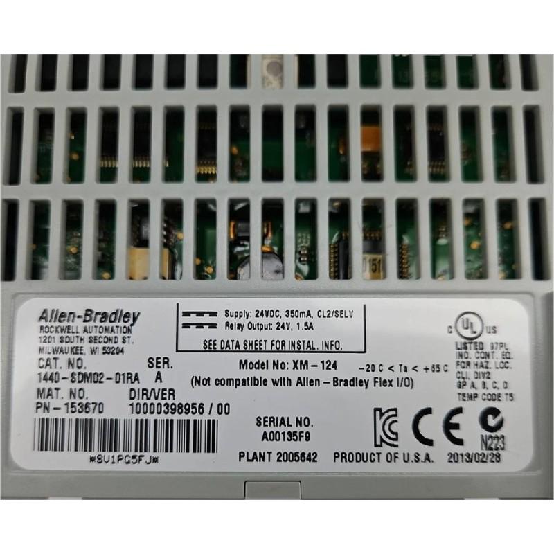
Allen-Bradley 1440-SDM02-01RA XM-124 Standard Dynamic Measurement Module Installation Guide
Time:2026-06-23 Browse: 1
Allen-Bradley 1440-SDM02-01RA XM-124 installation issues are most often caused by incorrect sensor wiring or grounding rather than module failure. In field commissioning of vibration monitoring systems, over 60% of startup delays we observed were related to improper transducer termination or tachometer noise coupling.
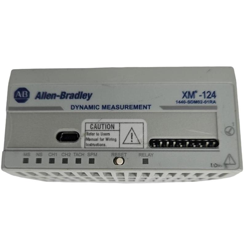
The XM-124 Standard Dynamic Measurement Module is a 2-channel dynamic monitoring module used for vibration, pressure, and eccentricity measurement in rotating machinery such as pumps, compressors, and turbines. It supports IEPE accelerometers, eddy current probes, and voltage-output sensors.
XM-124 System Role in Machine Protection Architecture
In a typical Allen-Bradley XM condition monitoring system, the 1440-SDM02-01RA acts as a front-end dynamic signal acquisition module. It processes raw analog signals and converts them into:
RMS vibration values
FFT spectrum data
Tachometer-based speed tracking
Alarm triggers (Alert / Danger / Fault)
We often deploy it in compressor train protection systems, where synchronous vibration tracking is required during startup and coast-down.
Preparation Before XM-124 Installation
Before wiring the module, engineers must confirm:
24V DC Class 2 / SELV power supply stability
Proper DIN rail grounding continuity (<1Ω recommended)
Sensor type compatibility:
IEPE accelerometers (4 mA bias)
Eddy current proximity probes
±10V / 0–20V signal sources
In one commissioning case on a gas compressor skid, unstable 24V supply ripple caused false tachometer triggering at 1200 rpm, which disappeared after replacing the PSU with a low-noise industrial unit.
XM-124 Terminal Wiring Considerations
The XM-124 terminal layout is highly sensitive to grounding loops.
Key connections include:
Channel 1 / Channel 2 dynamic inputs
Tachometer input (±25V max, 1–50,000 pulses/rev)
Two isolated 4–20 mA outputs
Signal return and chassis ground points
A common field mistake is tying signal common and chassis ground directly at multiple points, which introduces low-frequency vibration noise (~5–15 Hz artifacts).
We typically recommend single-point grounding at cabinet star earth busbar.
Commissioning Strategy for XM-124
Commissioning should follow a signal-first validation approach rather than software configuration first.
1. Raw Signal Validation
Before enabling XM software:
Check sensor DC bias voltage (IEPE ~10–14V typical)
Verify tachometer pulse stability using oscilloscope
Confirm channel noise floor (<5 mV RMS baseline)
2. Dynamic Response Test
We simulate shaft rotation or use run-up data:
Validate synchronous waveform tracking
Confirm FFT peak alignment at 1X rotational speed
In one pump system test, misaligned tach scaling caused incorrect 1X peak detection at 0.7X frequency—resolved by correcting pulse-per-rev configuration.
XM-124 Commissioning Verification
A properly installed module should show:
Stable RMS vibration baseline (<2 mm/s in idle pumps)
No intermittent “Transducer Fault” alarms
Consistent tach signal without dropouts
After final calibration, alarm thresholds can be enabled for:
Alert: 4.5 mm/s
Danger: 7.1 mm/s
Conclusion
Proper Allen-Bradley 1440-SDM02-01RA installation depends more on signal integrity and grounding discipline than software configuration. In industrial practice, stable wiring design reduces commissioning time by up to 40%.

