Honeywell 05701-A-0301 Single Channel Control Card Troubleshooting Guide
Time:2026-07-14 Browse: 19
Honeywell 05701-A-0301 Fault Symptoms and Initial Diagnosis
Honeywell 05701-A-0301 Troubleshooting usually begins when operators observe unstable readings, unexpected alarms, or channel fault conditions. In industrial environments, these symptoms do not always indicate a damaged control card. Engineers must first determine whether the problem originates from the sensor, wiring, power supply, or internal processing.
The Honeywell 05701-A-0301 Fault Diagnosis process should follow the actual signal flow instead of replacing components randomly.
The diagnostic path is:
Field Sensor → Signal Loop → Control Card Input → Alarm Processing
This method helps maintenance teams identify the real cause faster and avoid unnecessary module replacement.
Honeywell 05701-A-0301 Signal Analysis During Fault Diagnosis
Signal behavior provides important information during troubleshooting.
A constant low reading may indicate sensor output loss or an open signal loop.
A rapidly changing reading may suggest electrical interference, poor grounding, or unstable sensor output.
A permanent fault indication may be related to configuration problems, sensor interface issues, or communication interruption.
During troubleshooting, engineers should measure:
DC supply voltage
Signal current stability
Terminal connection condition
Sensor output response
For example, a normal zero-condition sensor signal should remain close to the expected minimum current. If the signal repeatedly drops below the normal operating range, the problem should be investigated before replacing the Honeywell 05701-A-0301 Control Card.
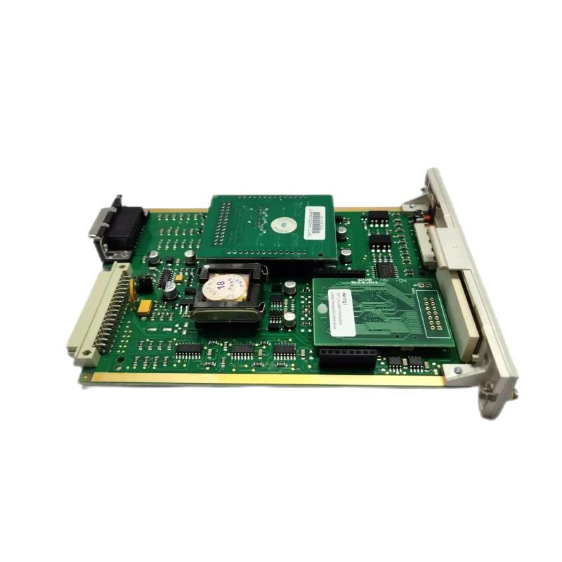
Honeywell 05701-A-0301 Real Field Case: Intermittent Fault Investigation
During maintenance at a wastewater treatment facility, operators reported that one Honeywell 05701-A-0301 channel occasionally entered fault mode without any actual gas event.
The engineering team collected operating data:
The control panel voltage remained stable at 24.3VDC.
The normal sensor loop current was around 4.06mA.
During the fault condition, the signal temporarily dropped to 3.2mA.
Initial inspection focused on the sensor because the fault appeared randomly.
However, further observation showed the fault occurred whenever a nearby motor drive started.
The investigation found that the sensor cable was routed close to a high-power electrical cable, causing signal interference.
After improving cable separation and correcting the shielding method, the loop signal remained stable between 4.05mA and 4.10mA.
The Honeywell 05701-A-0301 module continued operating normally without replacement.
Honeywell 05701-A-0301 Control Card Hardware Fault Investigation
Before considering Honeywell 05701-A-0301 Repair or replacement, engineers should confirm whether the failure follows the module or remains in the external circuit.
A proper hardware investigation includes:
Checking supply voltage stability
Testing input signal accuracy
Inspecting connector condition
Reviewing System Configuration
Confirming sensor compatibility
A genuine control card failure usually produces consistent symptoms, such as:
No display response
No normal signal processing
Incorrect output despite stable input conditions
In many industrial maintenance cases, loose terminals, damaged field cables, or incorrect settings are more common than actual electronic failure.
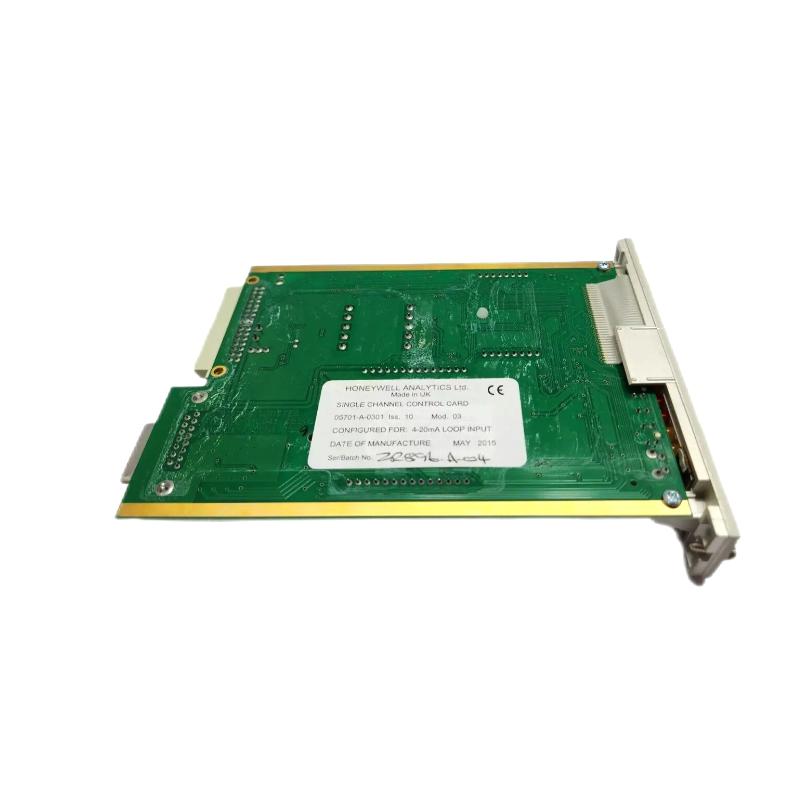
Honeywell 05701-A-0301 Alarm Recovery and Troubleshooting Method
After identifying and correcting the root cause, the Honeywell 05701-A-0301 Troubleshooting process should continue with functional verification.
Engineers should confirm:
Sensor signal recovery
Alarm reset operation
Correct display response
Stable operation after restart
A repaired system should be tested under different signal conditions.
During one repair validation, engineers simulated:
4.00mA for normal operation.
10.00mA for intermediate measurement.
16.00mA for alarm activation.
The Honeywell 05701-A-0301 responded correctly throughout the test, confirming that the fault was removed.
Honeywell 05701-A-0301 Troubleshooting Strategy for Reliable Operation
Long-term reliability of the Honeywell 05701-A-0301 Module depends on continuous monitoring of field conditions.
Maintenance teams should regularly check:
Signal stability
Sensor calibration status
Power quality
Cable condition
Alarm configuration
A practical Fault Diagnosis approach always starts with measurement data and field evidence. By analyzing voltage, current signals, and operating conditions, engineers can accurately determine whether the problem comes from the sensor system, wiring, configuration, or the Honeywell 05701-A-0301 Single Channel Control Card.

