Allen-Bradley 1606-XLB240E/A Power Supply Installation Guide
Time:2026-08-07 Browse: 9
Overview of Allen-Bradley 1606-XLB240E/A Power Supply Installation
Allen-Bradley 1606-XLB240E/A power supply installation problems are usually related to incorrect AC wiring, insufficient load planning, or poor DC grounding rather than the power supply itself. In industrial control panels, this 1606-XLB240E/A Power Supply is commonly used to provide stable 24 VDC power for PLC Controller systems, I/O modules, sensors, relays, and industrial communication devices. The unit belongs to the Allen-Bradley XLB series and provides a 240 W output capacity with a 24–28 VDC adjustable output range.
From field commissioning experience, a properly installed PLC power supply should maintain a stable DC bus voltage during startup, switching operations, and sudden load changes. Voltage fluctuation at the PLC input terminals is often the first indication of incorrect setup.
Allen-Bradley 1606-XLB240E/A Power Supply Installation Preparation
Before installing the 1606-XLB240E/A Power Supply, engineers should verify the complete System Configuration, including input voltage, connected devices, and expected current consumption.
A typical preparation checklist includes:
Confirm AC input availability and protection rating.
Calculate total 24 VDC load current.
Check PLC Controller and Module power requirements.
Prepare proper DIN rail mounting space.
Separate high-current motor wiring from control power wiring.
In one commissioning project, an Allen-Bradley PLC panel experienced random controller resets during machine startup. The initial assumption was a PLC hardware fault, but measurements showed the 24 VDC supply dropped from 24.2 VDC to 19.6 VDC when solenoid valves energized. After reviewing the power distribution design, the engineer found that the original supply was overloaded. Replacing it with a correctly sized power supply eliminated the resets.
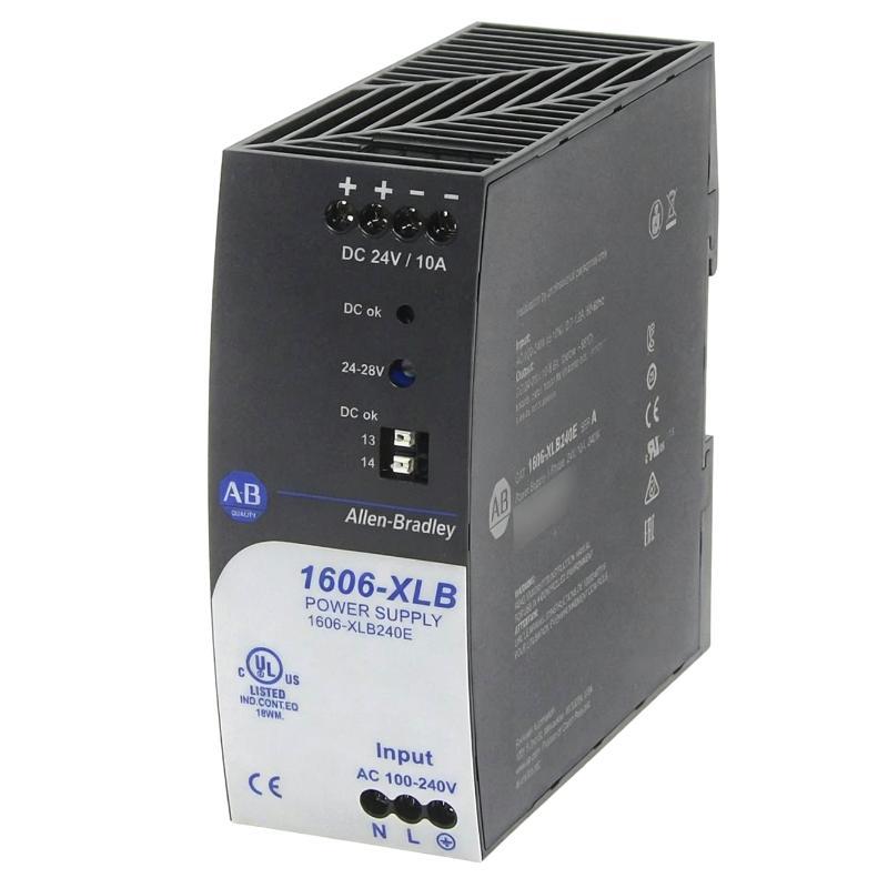
Allen-Bradley 1606-XLB240E/A Power Supply Wiring and Connection Setup
The wiring process of the Allen-Bradley 1606-XLB240E/A should focus on clean AC input connection and stable DC output distribution.
Recommended installation practices:
Connect AC Line and Neutral terminals according to the electrical drawing.
Use correctly rated circuit protection devices.
Connect +24 VDC and 0 VDC output terminals directly to the control power distribution points.
Keep DC negative grounding consistent throughout the control cabinet.
Avoid sharing PLC power wiring with heavy inductive loads.
The 1606-XLB240E/A uses screw terminals and supports single-phase AC input. The output provides regulated DC power suitable for industrial automation equipment.
During wiring inspection, engineers should verify:
Input voltage before energizing.
Output voltage without load.
Output voltage under full PLC load.
Voltage drop at remote devices.
Allen-Bradley 1606-XLB240E/A Power Supply Commissioning Procedure
The commissioning stage confirms that the Power Supply and connected PLC system operate correctly.
A practical commissioning sequence:
Measure AC input voltage.
Energize the power supply without external loads.
Check the DC output value.
Connect PLC Controller and Module circuits.
Monitor voltage stability during machine operation.
A normal commissioning measurement typically shows approximately 24 VDC at the control power terminals. If the voltage falls below the PLC operating range during equipment startup, further investigation should focus on cable size, load distribution, and peak current demand.
Allen-Bradley 1606-XLB240E/A Power Supply Setup Validation in PLC Systems
After installation, engineers should validate the complete control system rather than only checking whether the power LED is active.
The final validation should include:
PLC Controller startup test.
I/O module communication verification.
Sensor signal stability check.
Emergency stop circuit power test.
Machine restart test after power interruption.
A field engineer should always confirm the relationship between the 1606-XLB240E/A Power Supply and the entire automation system. A stable power source improves PLC reliability and prevents unnecessary troubleshooting caused by unstable DC voltage.

