Allen Bradley 1606-XLBUFFER Power Supply Installation Guide
Time:2026-08-10 Browse: 10
Allen Bradley 1606-XLBUFFER Power Supply Installation Overview
Allen Bradley 1606-XLBUFFER Power Supply installation requires correct DC wiring, load evaluation, and commissioning verification to ensure stable backup power performance in industrial automation systems. This 1606 series buffer unit is designed to support 24V DC control circuits by maintaining power availability during short voltage interruptions.
In field applications, the 1606-XLBUFFER is commonly installed together with PLC Controller systems, industrial I/O modules, and automation panels where unexpected DC voltage drops may cause controller resets or data loss. A proper Installation Guide focuses not only on wiring but also on System Configuration and real operating conditions.
Allen Bradley 1606-XLBUFFER Power Supply Preparation Before Setup
Before starting the Allen Bradley 1606-XLBUFFER Setup and Commissioning process, engineers should verify the complete power architecture.
The main inspection points include:
Confirm the 24V DC power source capacity.
Check the connection between the DC Power Supply and buffer unit.
Verify cabinet ventilation and DIN rail mounting position.
Measure input voltage before connecting the PLC Controller load.
The 1606-XLBUFFER operates with a nominal 24V DC system and supports buffering functions for industrial control applications. The unit provides a dedicated energy reserve to maintain DC supply stability when the main power source experiences short interruptions.
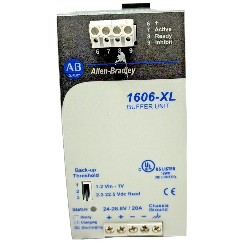
Allen Bradley 1606-XLBUFFER Wiring and System Configuration
Correct wiring is the foundation of reliable Power Supply operation.
During installation, the typical connection sequence includes:
Connect the 24V DC output of the main power supply to the buffer input terminals.
Connect the buffered output terminals to the PLC Controller or control circuit.
Confirm polarity before energizing the system.
Check protective grounding and cabinet wiring quality.
A common field mistake is connecting the buffer unit directly to a high-current actuator circuit. The 1606-XLBUFFER should normally protect sensitive automation electronics rather than unstable inductive loads.
In one commissioning case, a PLC system experienced random CPU restarts every few hours. The initial assumption was a PLC Controller fault. After checking the DC supply waveform, engineers found a voltage drop from 24.1V DC to 19.8V DC during motor contactor switching. After installing and correctly configuring the buffer unit, the voltage remained above 22.5V DC and the PLC stopped resetting.
Allen Bradley 1606-XLBUFFER Setup and Commissioning Verification
The commissioning process should include electrical measurement and functional testing.
Recommended checks:
Input voltage measurement: approximately 24V DC
Output voltage stability test
Buffer response during temporary power interruption
PLC Controller restart monitoring
DC alarm signal verification
During a practical Setup and Commissioning procedure, technicians should temporarily simulate a short power interruption and observe whether the automation system remains active.
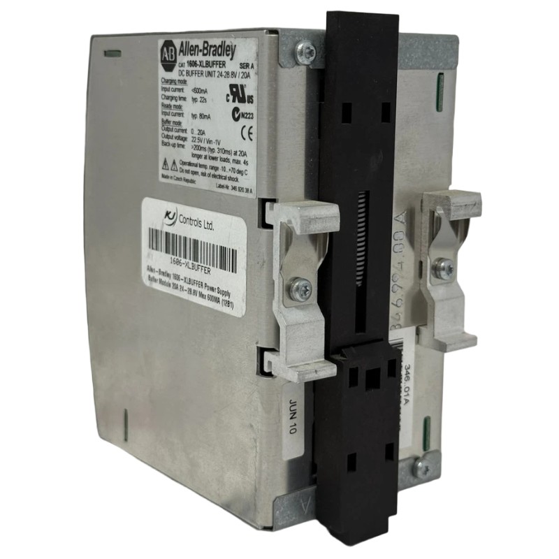
Allen Bradley 1606-XLBUFFER Installation Guide for Industrial Reliability Improvement
A successful Allen Bradley 1606-XLBUFFER Installation Guide is not only about connecting terminals. Engineers must understand the relationship between power quality, PLC Controller stability, and machine availability.
Field experience shows that many automation failures caused by short DC interruptions are incorrectly diagnosed as PLC hardware failures. Proper buffer installation improves system reliability and reduces unnecessary module replacement.

