Allen Bradley 1606-XLBUFFER Power Supply Fault Troubleshooting Guide
Time:2026-08-10 Browse: 10
Allen Bradley 1606-XLBUFFER Power Supply Fault Symptoms and Initial Analysis
Allen Bradley 1606-XLBUFFER Troubleshooting usually begins when PLC Controller systems experience unexpected shutdowns, communication loss, or DC voltage instability. The most common fault pattern is insufficient buffering performance caused by incorrect charging conditions, wiring problems, or excessive load demand.
A real troubleshooting case involved a packaging machine where the PLC Controller restarted during every large motor startup. The DC measurement showed a temporary voltage decrease from 24.3V DC to 20.4V DC, causing the control system to lose operation.
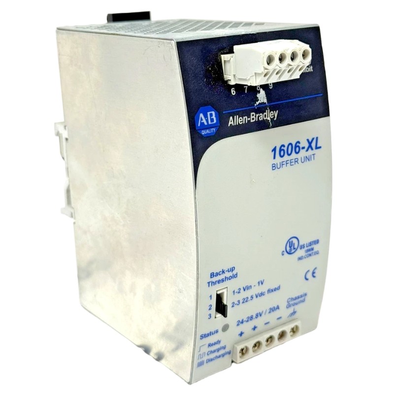
Allen Bradley 1606-XLBUFFER Fault Diagnosis Based on Voltage Measurement
The Fault Diagnosis process should start with electrical evidence rather than replacing components.
Engineers normally check:
DC input voltage level
Buffer charging status
Output voltage during load changes
Current consumption of connected devices
Terminal connection resistance
During diagnosis, we observed that the buffer unit input voltage was normal at 24.5V DC, but the output dropped significantly when the PLC Controller and communication modules entered peak operation.
Further analysis showed that additional field devices had been connected to the buffered output after the original commissioning. The increased current demand exceeded the expected operating condition.
Allen Bradley 1606-XLBUFFER Repair Action and Recovery Test
The corrective action included:
Removing unnecessary devices from the buffered circuit.
Separating motor-related loads from PLC protection circuits.
Improving cabinet wiring arrangement.
Repeating commissioning tests.
After correction, the DC voltage remained stable at approximately 24V DC during motor activation, and PLC Controller communication returned to normal operation.
The repair process confirmed that proper Fault Diagnosis requires analyzing the entire control power system rather than replacing individual components.
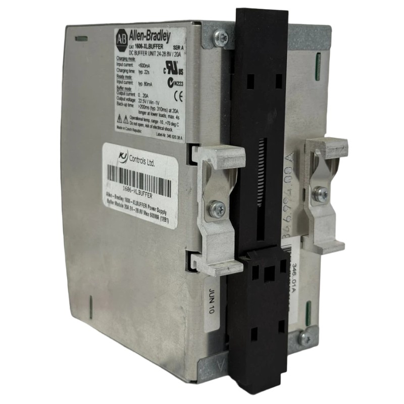
Allen Bradley 1606-XLBUFFER Troubleshooting Guide for Long-Term Operation
For long-term reliability, engineers should periodically inspect:
Terminal tightness
DC voltage stability
Load expansion changes
Cabinet temperature conditions
PLC Controller fault history
The 1606-XLBUFFER is a Power Supply support device, but its performance depends heavily on correct application design and System Configuration.
Experienced automation technicians usually verify power quality first because many PLC Controller faults are actually caused by unstable DC supply conditions. A structured Troubleshooting and Fault Diagnosis method can significantly reduce downtime and unnecessary hardware replacement.

