Allen-Bradley 1606-XLE240E Power Supply Troubleshooting Guide
Time:2026-08-17 Browse: 15
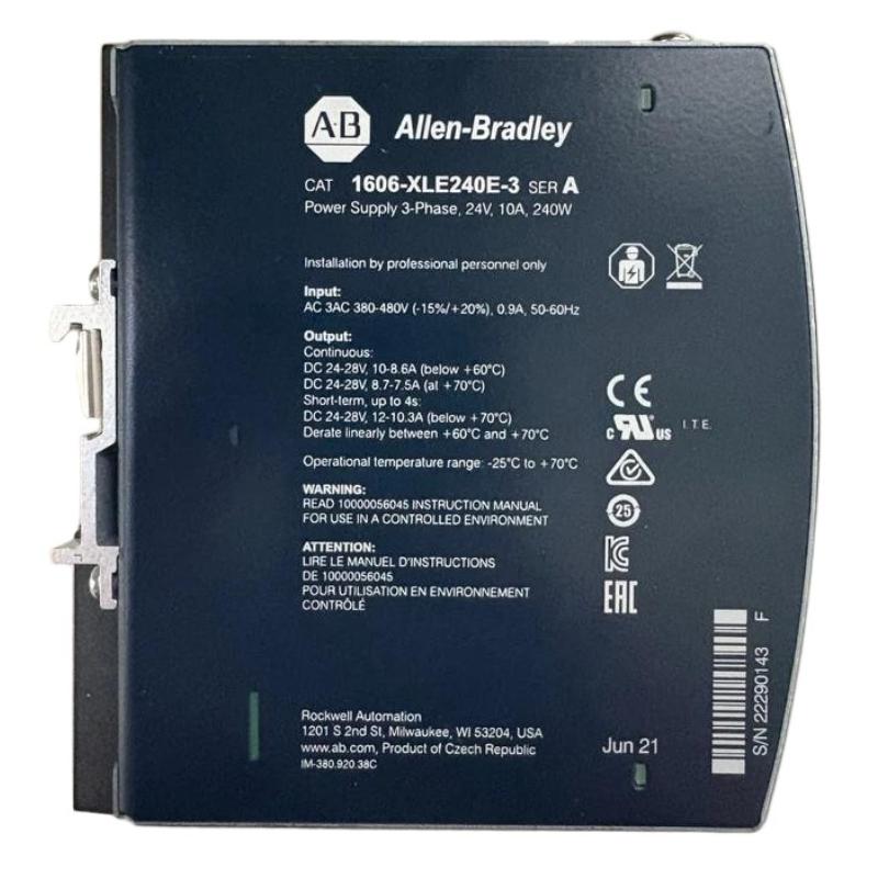
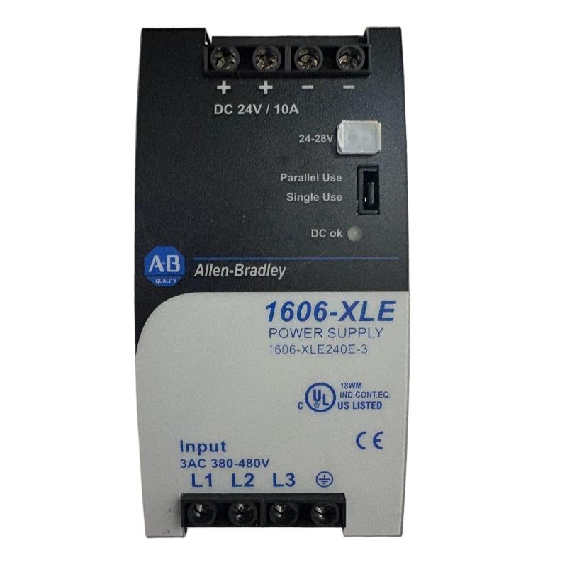
Allen-Bradley 1606-XLE240E power supply faults should be diagnosed by separating input problems, overload conditions, wiring faults, and downstream PLC or I/O problems. The 1606-XLE240E is rated for 24 VDC, 10 A, and 240 W, with a stabilized output and DC-OK monitoring, so a measured 24 VDC value alone is not enough to prove that the complete power system is healthy.
Allen-Bradley 1606-XLE240E Fault Symptoms
Typical symptoms associated with a suspected 1606-XLE240E fault include:
PLC controller unexpectedly restarting
I/O modules dropping offline
24 VDC output below the expected level
DC-OK indication changing state
Sensors intermittently losing power
Contactors or solenoids causing control-power disturbances
Power supply becoming unusually hot
Output recovering after a load is removed
The first diagnostic question should be whether the fault exists at the power supply output or only at the downstream equipment.
1606-XLE240E Troubleshooting: Start With the Input
When the output is missing, begin at the AC input rather than replacing the power supply.
Measure the voltage directly at the input terminals while the system is energized. If the expected AC supply is missing, investigate the upstream circuit breaker, fuse, contactor, disconnect, terminal block, or control transformer.
The 1606-XLE240E documentation specifies an external input fuse of B-6 A or C-6 A minimum and an input operating range of 90–132 VAC for the documented input configuration.
This distinction prevents a common maintenance error: replacing a perfectly functional power supply when the actual problem is upstream.
Allen-Bradley 1606-XLE240E Low-Voltage Fault Diagnosis
A low 24 VDC reading can originate from several different conditions:
Case A — Low voltage at the power supply terminals
Possible causes include overload, excessive temperature, input problems, or internal power-supply failure.
Case B — Normal voltage at the power supply but low voltage at the PLC
Possible causes include loose terminals, undersized conductors, excessive cable resistance, or a high-current downstream device.
Case C — Normal voltage at both locations but PLC still resets
Move the investigation toward the PLC Controller, I/O modules, grounding, communication equipment, or a device creating electrical interference.
This voltage-location comparison is one of the fastest ways to narrow the fault.
1606-XLE240E Overload Fault Investigation
The unit has a nominal output current rating of 10 A and 240 W output power, with a documented 20% power reserve. However, the reserve should not be treated as permission to design the system permanently at the absolute limit.
For troubleshooting, calculate the actual DC load:
I_total = I_PLC + I_I/O + I_sensor + I_relay + I_other
If the calculated load is unexpectedly high, isolate branch circuits one at a time.
For example, if the control cabinet normally draws 5.5 A but rises sharply when several solenoid valves energize, disconnecting individual branches can identify whether the apparent power-supply fault is actually caused by a downstream load.
Allen-Bradley 1606-XLE240E Thermal Fault Diagnosis
Temperature-related faults can be misleading because the power supply may operate normally immediately after a cold start and fail only after extended machine operation.
The 1606-XLE240E has a specified derating figure of 6 W/°C. The manufacturer also lists an operating temperature starting at -25°C.
A practical field test is to compare:
Cabinet temperature at startup
Cabinet temperature when the fault appears
1606-XLE240E output voltage at both times
Total DC current at both times
If the fault appears only after prolonged operation and disappears after cooling, thermal loading becomes a stronger suspect.
Allen-Bradley 1606-XLE240E DC-OK Fault Troubleshooting
The 1606-XLE240E provides a DC-OK relay contact that can be connected to the control system.
If the PLC reports a power-supply fault, do not rely exclusively on the PLC diagnostic bit.
Compare three pieces of information:
PLC diagnostic status → DC-OK contact → measured DC voltage
If the PLC reports a fault while the measured voltage remains stable, inspect the DC-OK circuit and System Configuration.
If the DC-OK status changes at the same time that the physical DC voltage falls, investigate the power supply or its load.
If the DC-OK status remains normal while the PLC loses power, measure voltage directly at the PLC terminals and investigate the distribution path.
1606-XLE240E Fault Diagnosis: A Downstream Short Circuit
One particularly useful troubleshooting pattern is an intermittent short circuit on a 24 VDC branch.
The power supply may appear healthy until a damaged sensor cable, solenoid coil, or field device becomes active. At that point, the control voltage may collapse or the affected branch may disturb the complete DC distribution.
A practical isolation method is to remove nonessential branches and restore them individually while monitoring the 24 VDC output.
If the supply becomes stable immediately after one branch is disconnected, inspect that branch before condemning the 1606-XLE240E.
Allen-Bradley 1606-XLE240E Repair Decision Process
Before replacing the power supply, collect these measurements:
| Diagnostic Point | Normal Observation | Fault Direction |
|---|---|---|
| AC input | Correct supply voltage | Upstream circuit |
| DC output | Near configured 24 VDC | Power supply or load |
| PLC input voltage | Stable | Distribution wiring |
| DC-OK contact | Expected state | Relay/control circuit |
| DC current | Within design range | Overload if excessive |
| Cabinet temperature | Within design conditions | Thermal investigation |
A replacement should be considered only after the input, load, wiring, and operating environment have been checked.
This approach is especially important for intermittent faults because a replacement unit may temporarily appear to solve the problem while leaving the actual field fault untouched.
Allen-Bradley 1606-XLE240E Field Fault Case
A representative field troubleshooting pattern involved a PLC controller that restarted whenever several output devices changed state at the same time.
The first measurement showed a stable 24 VDC value while the machine was idle. That result initially suggested that the 1606-XLE240E was functioning correctly.
The next measurement was taken during the actual fault event. The voltage at the PLC input dropped while the voltage at the power-supply terminals remained substantially more stable. The diagnostic path therefore shifted away from the power supply.
Inspection of the DC distribution found a high-resistance connection at a terminal point feeding the PLC branch. After the terminal was corrected, the same machine sequence was repeated and the PLC reset no longer occurred.
The important Fault Diagnosis principle is that the measurement must be taken when the fault happens. A static voltage check can miss a transient power-distribution problem.
1606-XLE240E Troubleshooting and Repair Checklist
For a failed 1606-XLE240E installation, use this diagnostic order:
Verify the AC input.
Inspect the input protection.
Measure DC output directly at the power supply.
Check total DC load current.
Measure voltage at the affected PLC or Module.
Compare supply-side and load-side voltage.
Inspect DC terminals and distribution blocks.
Isolate high-current or suspicious branches.
Check DC-OK relay status.
Evaluate cabinet temperature and ventilation.
Replace the power supply only after external causes have been eliminated.
Allen-Bradley 1606-XLE240E Troubleshooting Long-Tail Keywords
This Troubleshooting Guide covers common searches including:
Allen-Bradley 1606-XLE240E troubleshooting
1606-XLE240E fault diagnosis
1606-XLE240E power supply not working
1606-XLE240E 24VDC output fault
1606-XLE240E low voltage problem
1606-XLE240E PLC reset troubleshooting
Allen-Bradley 1606-XLE240E overload fault
1606-XLE240E DC-OK fault
1606-XLE240E power supply repair
1606-XLE240E PLC power fault
1606-XLE240E System Configuration fault
Allen-Bradley 1606-XLE240E Module power troubleshooting
Allen-Bradley 1606-XLE240E Fault Diagnosis Conclusion
The most effective 1606-XLE240E Troubleshooting method is measurement-based: verify the AC input, observe the 24 VDC output under load, compare the power-supply voltage with the PLC-side voltage, and isolate downstream circuits before replacing hardware. The 1606-XLE240E is a 240 W, 24 VDC, 10 A stabilized power supply with DC-OK monitoring, so its diagnostic signals can be used together with direct electrical measurements to distinguish a genuine power-supply failure from a distribution or load problem.

