Allen-Bradley 1606-XLE240E Power Supply Installation Guide
Time:2026-08-17 Browse: 13
The Allen-Bradley 1606-XLE240E is a 240 W industrial power supply designed to provide a regulated 24 VDC supply for PLC controllers, I/O modules, sensors, relays, and other automation equipment. For a reliable installation, the main engineering checks are input voltage, output loading, terminal wiring, grounding, ventilation, and DC-OK monitoring. The unit provides up to 10 A at 24 VDC and has a 20% power reserve under its specified conditions.
Allen-Bradley 1606-XLE240E Power Supply General Information
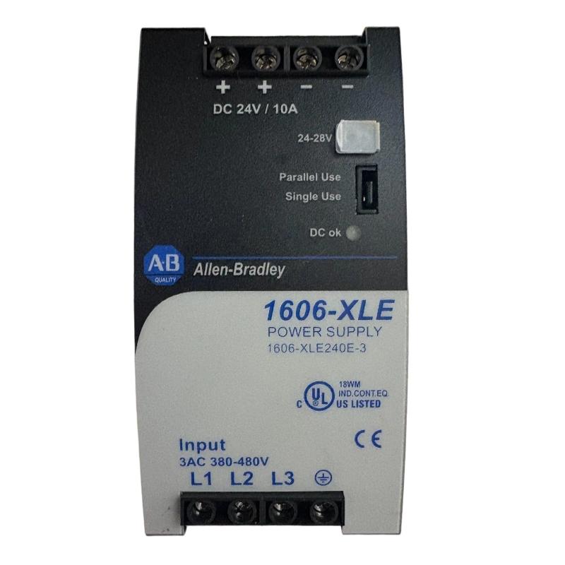
The 1606-XLE240E belongs to the Allen-Bradley XLE Essential power supply family. It accepts 120/240 V-class single-phase AC input and provides a stabilized 24–28 VDC output range. The nominal output is 24 VDC at 10 A, with 240 W maximum output power.
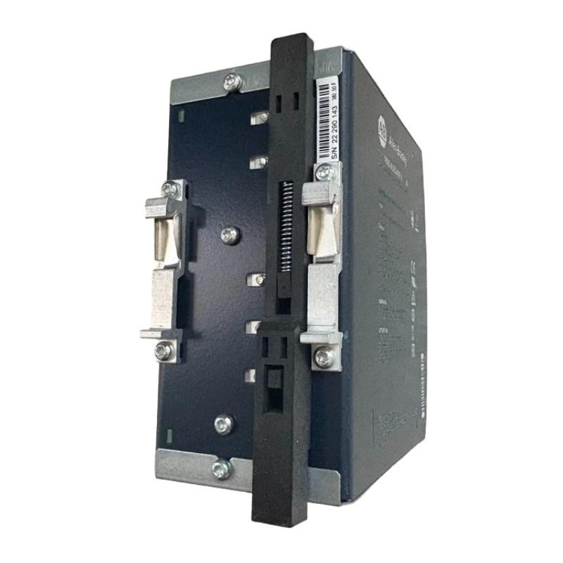
The power supply uses screw terminals and supports DIN-rail mounting. Its compact housing is approximately 39 mm wide, 124 mm high, and 117 mm deep, with a weight of about 600 g.
Key specifications
Brand: Allen-Bradley
Model: 1606-XLE240E
Type: Industrial Power Supply
Output: 24 VDC nominal
Output range: 24–28 VDC
Maximum output current: 10 A
Rated power: 240 W
Efficiency: approximately 95.2% typical
Protection rating: IP20
Connection: Screw terminals
Mounting: DIN rail
Country of Origin: Czechia
1606-XLE240E Installation Preparation
Before applying power, confirm that the actual supply voltage matches the installation requirements. The 1606-XLE240E has an input operating range of approximately 90–132 VAC for the documented input configuration, so the incoming supply must be verified before wiring.
Check the expected DC load as well. A 24 VDC load drawing 8 A represents approximately 192 W, leaving useful operating margin below the 240 W rating. When several PLC modules, field sensors, Ethernet devices, and relays share the same supply, calculate the combined continuous current rather than sizing the supply from the PLC controller alone.
A practical installation check should include:
Verify AC supply voltage with a calibrated meter.
Confirm protective-device sizing.
Inspect terminal condition and conductor size.
Calculate the total 24 VDC load.
Leave reasonable capacity for startup and future expansion.
Provide adequate clearance for heat dissipation.
Verify the cabinet grounding arrangement.
Allen-Bradley 1606-XLE240E Wiring and Terminal Checks
The input and output conductors should be separated as required by the cabinet design, particularly where high-current switching devices or variable-frequency drives are installed nearby.
The DC output should be wired with correct polarity. Reverse or incorrect field wiring can cause immediate problems for PLC I/O modules and sensors connected downstream.
The 1606-XLE240E also provides a DC-OK relay contact. This signal can be incorporated into the PLC Controller system configuration so that the controller can detect a power-supply condition without relying only on the power supply's physical indicator.
For a typical control cabinet, the engineering logic is:
AC source → 1606-XLE240E → 24 VDC distribution → PLC / I/O / sensors / relays
Keep high-noise circuits physically separated from sensitive analog or communication wiring whenever possible.
1606-XLE240E Output Voltage Setup
The nominal output is 24 VDC, while the documented adjustment range extends to 28 VDC. Do not increase the output simply because a higher voltage is available.
For a PLC system designed around 24 VDC, the normal setup should remain close to the equipment manufacturer's required supply voltage. Measure the voltage at the power supply and, when troubleshooting a long distribution circuit, measure again at the remote load.
A useful commissioning comparison is:
VPSU = voltage at power supply
VLOAD = voltage at field device
If VPSU is stable but VLOAD drops significantly when the machine starts, investigate distribution resistance, terminal connections, cable sizing, or a downstream load rather than immediately replacing the power supply.
Allen-Bradley 1606-XLE240E Setup and Commissioning
After wiring has been inspected, energize the AC input and verify the DC output before connecting sensitive loads where the commissioning procedure permits isolated testing.
A practical commissioning sequence is:
Confirm the incoming AC voltage.
Energize the 1606-XLE240E.
Measure the DC output with no or limited load.
Confirm approximately 24 VDC under normal setup.
Apply the PLC and I/O load.
Monitor the output while the machine enters its normal operating state.
Check the DC-OK indication/contact.
Record the measured voltage and load condition.
The manufacturer specifies typical ripple and noise of up to 50 mV, approximately 95.2% typical efficiency, and a 20% power reserve. These values are useful reference points when evaluating abnormal output behavior during commissioning.
1606-XLE240E Commissioning Validation in a Control Cabinet
A common field commissioning mistake is checking the power supply only with the machine stopped. A supply may show a healthy 24 VDC reading with no load and still experience a voltage problem when solenoids, contactors, sensors, and I/O modules become active.
A better validation method is to measure the output during three conditions:
PLC powered with normal idle load
Machine operating under normal sequence
Highest expected simultaneous DC load
If the voltage remains stable during the third condition, the power distribution is much more likely to be reliable in normal production.
Allen-Bradley 1606-XLE240E Field Commissioning Case
In a representative cabinet commissioning case, a 24 VDC control system showed intermittent PLC I/O resets during machine startup. The initial assumption was a defective power supply because the reset occurred when multiple loads energized simultaneously.
The diagnostic process compared the power-supply output during idle and startup conditions. The supply itself remained close to its nominal output, while the voltage measured farther downstream dropped noticeably during the load transition.
The investigation therefore moved from the 1606-XLE240E to the distribution circuit. A loose DC terminal connection was found in the downstream distribution block. After the connection was corrected, the voltage remained stable during the same startup sequence.
The engineering lesson is important: an intermittent PLC fault does not automatically mean that the 1606-XLE240E is defective. Always compare the supply-terminal voltage with the voltage measured at the affected load.
Allen-Bradley 1606-XLE240E Installation Troubleshooting
If commissioning fails, use the following diagnostic logic:
No output:
Check AC input, upstream protection, terminal wiring, and the power supply indicators.
Output is present but PLC resets:
Measure voltage directly at the PLC during the reset event. Then compare it with the voltage at the power supply.
Output falls when loads start:
Check total current, startup loads, distribution wiring, terminal resistance, and short-duration overload conditions.
DC-OK signal is abnormal:
Check the relay wiring and the actual DC output independently before concluding that the relay circuit has failed.
Excessive cabinet temperature:
Review cabinet ventilation, ambient temperature, loading, and heat dissipation. The manufacturer specifies a 6 W/°C derating figure.
Allen-Bradley 1606-XLE240E Long-Tail Installation Keywords
This Installation Guide is relevant to searches for:
Allen-Bradley 1606-XLE240E installation
Allen-Bradley 1606-XLE240E wiring guide
1606-XLE240E power supply setup
1606-XLE240E 24VDC commissioning
Allen-Bradley 1606-XLE240E DIN rail installation
1606-XLE240E PLC power supply
1606-XLE240E DC-OK wiring
1606-XLE240E output voltage troubleshooting
1606-XLE240E System Configuration
Allen-Bradley industrial power supply installation
Allen-Bradley 1606-XLE240E Installation Summary
The 1606-XLE240E should be commissioned as part of the complete 24 VDC control-power system rather than as an isolated component. Verify the AC input, output voltage, load current, wiring integrity, thermal conditions, and DC-OK status before releasing the cabinet for operation. The manufacturer's documentation identifies the unit as a 240 W, 24 VDC, 10 A XLE power supply with stabilized output and DIN-rail mounting capability.

