GE DS200TCEBG1BAA Protection Terminal Expansion Board Troubleshooting Guide
Time:2026-08-18 Browse: 15
GE DS200TCEBG1BAA troubleshooting should start with the protection signal path rather than immediately replacing the board. When a MARK V protection indication is missing, intermittent, or incorrect, the fault may originate in field wiring, terminal connections, connectors, configuration, or the board itself.
GE DS200TCEBG1BAA Fault Symptoms in MARK V Systems
Typical symptoms can include:
A protection input remains in the wrong state
A field signal is not recognized
An expected protection indication does not appear
A signal changes intermittently
The system reports an unexpected protection condition
A previously stable signal disappears after cabinet maintenance
The important distinction is whether the problem follows the field signal, the wiring, or the DS200TCEBG1BAA signal path.
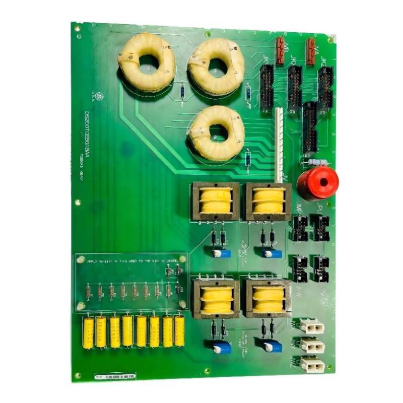
GE DS200TCEBG1BAA Fault Diagnosis: Start at the Terminal
A useful troubleshooting method is to begin at the point where the field signal enters the cabinet.
In one practical diagnostic case, a protection input remained inactive even though the external device had operated correctly. The first assumption was a failed board. However, voltage measurement at the field circuit showed the expected signal, while measurement at the cabinet terminal showed an unstable reading.
The investigation then moved in this order:
Field device → field cable → cabinet terminal → DS200TCEBG1BAA connection → control-system indication
This quickly narrowed the problem to the cabinet wiring rather than the PCB.
GE DS200TCEBG1BAA Intermittent Signal Troubleshooting
Intermittent faults deserve special attention because they can disappear during a normal visual inspection.
Check the terminal connection while monitoring the affected signal. Look for a change in voltage or continuity when the cable is moved slightly under controlled maintenance conditions.
For a nominal 24 VDC control signal, an observed sequence such as:
24.1 V → 18.7 V → 24.0 V
during a controlled cable movement indicates a connection or conductor problem that would not be identified by simply looking at the board.
Do not repeatedly reseat a connector and consider the problem solved. If reseating restores operation, inspect the connector, pins, socket condition, and mechanical alignment to identify why the signal was interrupted.
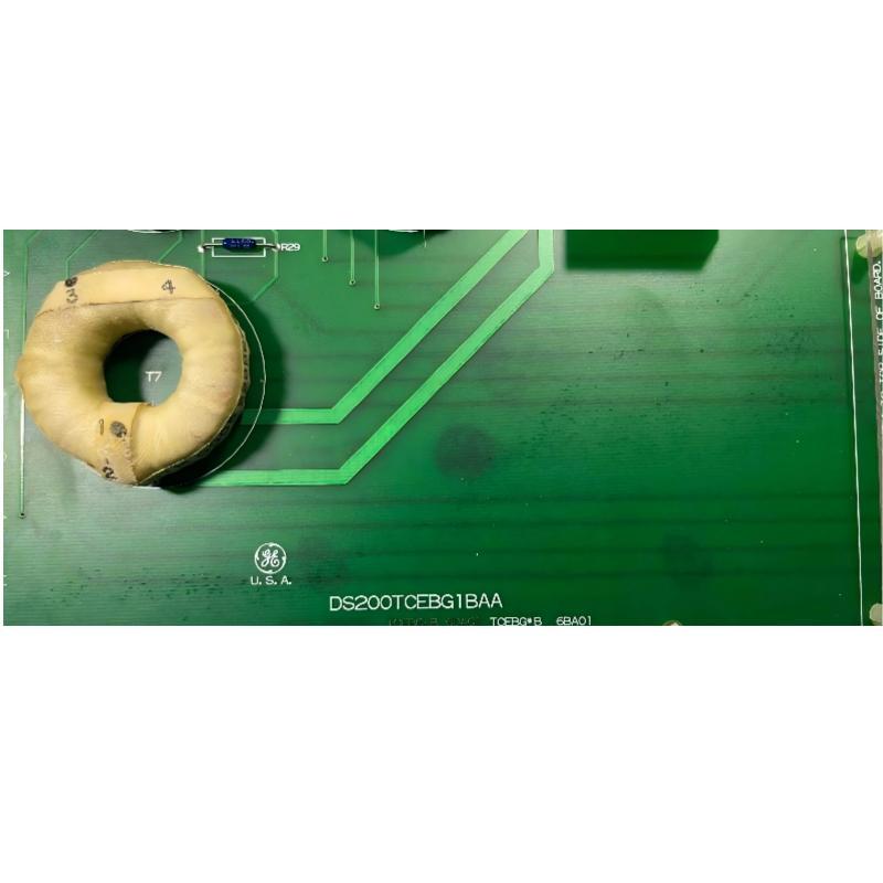
GE DS200TCEBG1BAA Protection Signal Fault: Configuration Check
If the electrical signal reaches the board correctly but the MARK V system still shows the wrong status, move the Fault Diagnosis process toward System Configuration and signal interpretation.
Compare the actual terminal assignment with:
Electrical drawings
Signal descriptions
Cabinet documentation
Control logic
Relevant configuration records
This distinction is important because a correct electrical signal can still produce an incorrect system indication if it is assigned or interpreted incorrectly.
GE DS200TCEBG1BAA Board-Level Troubleshooting
Only after the external signal path has been verified should the DS200TCEBG1BAA itself become the primary suspect.
Inspect the board for:
Burn marks
Damaged components
Discolored PCB areas
Loose connectors
Contamination
Mechanical damage
Abnormal connector seating
If a replacement board is available, controlled substitution can help confirm the diagnosis. However, the replacement should have compatible hardware and revision characteristics for the installed MARK V system.
A board swap is useful as a diagnostic method, but it should not replace electrical testing.
GE DS200TCEBG1BAA Repair and Recovery Verification
After correcting the fault, repeat the original test that exposed the problem. Verify both the physical signal and the resulting MARK V indication.
A good recovery record should include:
Fault condition → measured value → corrective action → post-repair measurement → system response
For example, if a loose terminal caused an intermittent 24 VDC protection signal, the final test should demonstrate a stable signal under the applicable operating or test condition rather than simply confirming that the alarm disappeared.
GE DS200TCEBG1BAA Troubleshooting Long-Tail Keywords
Relevant long-tail search terms for this Fault Diagnosis process include:
GE DS200TCEBG1BAA troubleshooting guide
GE DS200TCEBG1BAA fault diagnosis
DS200TCEBG1BAA protection signal fault
GE MARK V protection board troubleshooting
DS200TCEBG1BAA terminal signal problem
GE DS200TCEBG1BAA intermittent fault
DS200TCEBG1BAA repair procedure
GE MARK V protection terminal troubleshooting
The key field principle is simple: prove the signal path before condemning the board. This approach reduces unnecessary board replacement and makes MARK V Troubleshooting more systematic.

