GE DS200TCEBG1BAA MARK V Protection Terminal Expansion Board Installation Guide
Time:2026-08-18 Browse: 14
GE DS200TCEBG1BAA installation should begin with terminal identification, board condition checks, and a review of the existing MARK V System Configuration. As a protection terminal expansion board, the DS200TCEBG1BAA is installed within a larger control and protection system, so incorrect wiring or terminal placement can affect signal integrity and protection logic.
GE DS200TCEBG1BAA Board Installation Preparation
Before removing the existing board or installing the replacement, record the field wiring and terminal assignments. Do not rely only on wire color because older MARK V installations may contain modified or site-specific wiring.
A practical preparation check should include:
DS200TCEBG1BAA board identification
Terminal and connector labeling
Existing cable routing
Board mounting condition
Connector condition
Cabinet grounding
MARK V System Configuration records
Replacement board revision and hardware condition
In one field replacement case, several wires appeared to have identical insulation colors. The engineer photographed the original terminal arrangement and marked each conductor before removal. This avoided reversing two protection-related signals during commissioning.
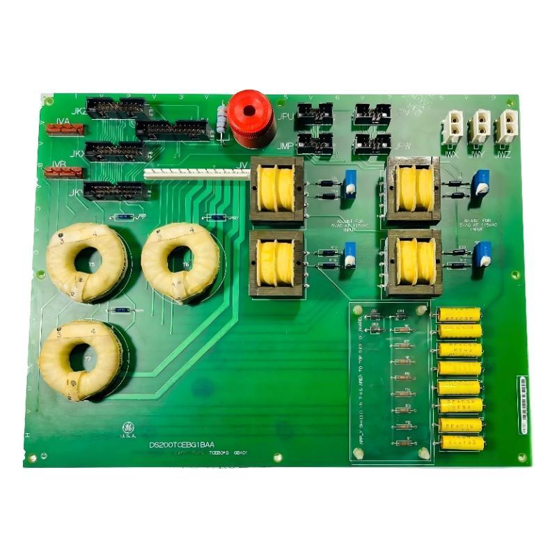
GE DS200TCEBG1BAA Wiring and Terminal Checks
The wiring stage is more important than simply securing the board mechanically. Each conductor should be matched against the approved cabinet drawings and the original terminal assignment.
Check for:
Loose terminal screws
Damaged insulation
Oxidized conductors
Incorrect wire routing
Bent connector pins
Excessive cable tension
The DS200TCEBG1BAA should be firmly mounted without stressing the PCB or attached wiring. Field cables should have enough slack to prevent mechanical force from being transferred to the terminals.
GE DS200TCEBG1BAA Setup and System Configuration
After physical installation, review the MARK V System Configuration before energizing the control system. The purpose is to confirm that the installed hardware corresponds to the intended protection signal path.
A useful commissioning sequence is to compare:
Drawing → Terminal → Board → Signal → Control logic
If these five points agree, troubleshooting later becomes considerably easier.
Do not immediately assume that a missing protection indication means the DS200TCEBG1BAA is defective. A configuration mismatch, open field circuit, connector problem, or upstream signal issue can produce similar symptoms.
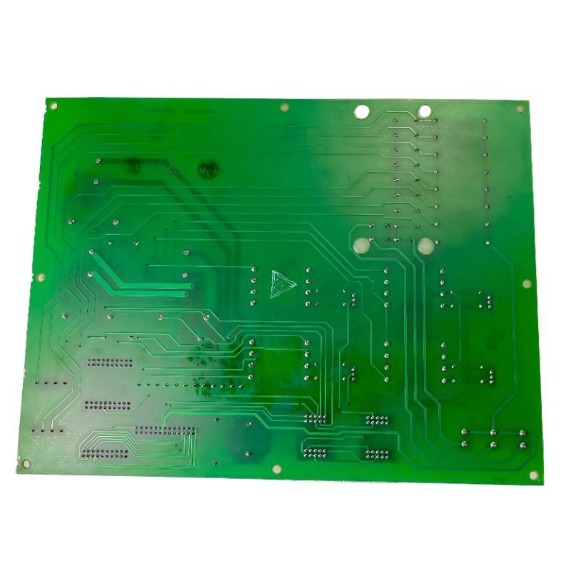
GE DS200TCEBG1BAA Commissioning and Signal Validation
During commissioning, verify the relevant input and output signals individually rather than testing the entire protection circuit at once.
Record the expected signal state and the actual observed state. Where test equipment is available, measure the relevant circuit voltage or continuity according to the site test procedure.
For example, if a protection input is expected to change state during a controlled test, document the signal before and after activation. A simple record such as:
Normal: 24 VDC → Test condition: 0 VDC → Return: 24 VDC
provides much more useful information than simply recording “test passed.”
GE DS200TCEBG1BAA Installation Fault Prevention
The most common installation-related problems are not necessarily PCB failures. Field wiring mistakes, poor connector seating, incorrect terminal identification, and incomplete System Configuration checks can all create commissioning faults.
Keep the original wiring documentation with the replacement record. If the board is later removed for Troubleshooting or Fault Diagnosis, the next engineer can reconstruct the signal path without repeating the entire identification process.
GE DS200TCEBG1BAA Installation Guide Long-Tail Keywords
This Installation Guide naturally covers several relevant search terms, including:
GE DS200TCEBG1BAA installation guide
GE DS200TCEBG1BAA setup procedure
GE DS200TCEBG1BAA commissioning
DS200TCEBG1BAA MARK V protection board installation
GE MARK V terminal expansion board wiring
DS200TCEBG1BAA System Configuration
GE DS200TCEBG1BAA signal verification
DS200TCEBG1BAA field wiring check
The objective is not simply to install the board, but to establish a verified signal path before the MARK V system is returned to service.

