GE 104X905BA603 Display Panel with Keypad Installation Guide
Time:2026-08-20 Browse: 15
GE 104X905BA603 installation is primarily concerned with correct panel mounting, keypad connection, display operation, and interface compatibility. The 104X905BA603 is identified as a GE display panel with keypad for DCC/SDCC-related control boards, and available parts references also associate it with GE drive and EX2000 control applications.
GE 104X905BA603 Display Panel Installation Preparation
Before installing the GE 104X905BA603, isolate the associated control equipment and verify that the replacement panel matches the existing hardware.
The most important checks are:
Confirm the complete part number: 104X905BA603.
Check the panel style and frame against the existing installation.
Inspect the keypad membrane for cracks, deformation, or damaged keys.
Check the display connector and ribbon cable for bent or contaminated contacts.
Verify the host control board before connecting the panel.
Record the original cable orientation before removal.
Available technical references describe the unit as a Display Panel with Keypad, with one source specifically identifying it for DCC/SDCC boards.

GE 104X905BA603 Panel Mounting and Interface Setup
The panel should be mechanically secure but should not be forced into position. If the mounting surface is misaligned, excessive pressure can transfer directly to the display assembly or connector.
The electrical interface is equally important. A replacement display should be connected using the original interface arrangement rather than assuming that a visually similar GE keypad uses the same wiring.
One parts reference identifies the 104X905BA603 as a 20-button display/keypad assembly, while another source lists it as an HMI/MMI/OIT keypad component.
This distinction matters during Setup because the keypad is not simply a passive label panel. Operator key input and display information form part of the local control interface.
GE 104X905BA603 Display Panel Setup and Commissioning
After mechanical installation, energize the associated control system only after checking the connector seating.
During commissioning, verify the interface in this order:
Power-up → display initialization → keypad response → control-system communication → operator function
The first useful observation is whether the display initializes normally. If the screen remains completely inactive, investigate the supply and interface path before assuming a keypad failure.
If the display operates but individual keys do not respond, the diagnostic direction changes toward the keypad assembly, connector, or key-switch circuit.
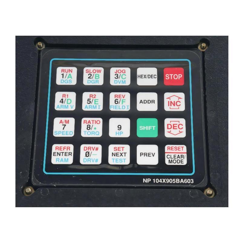
GE 104X905BA603 Installation Case: Intermittent Keypad Response
In one field-style replacement case, an operator reported that several keys worked only when the front panel was pressed firmly.
The initial assumption was a defective keypad. However, the symptom changed when the panel was moved slightly, which suggested a mechanical or connector-related problem rather than a software issue.
Inspection found that the interface connection was not seated consistently. After removing contamination, reseating the connector, and securing the panel correctly, repeated keypad tests produced stable responses.
The engineering lesson is simple: when keypad behavior changes with physical pressure, inspect the mechanical installation and connector before replacing the entire panel.
GE 104X905BA603 Display Panel Validation
A completed Setup / Commissioning check should include:
Display starts correctly.
All required keypad functions respond.
No keys remain permanently active.
Operator commands are correctly recognized by the host system.
The display remains stable during normal equipment operation.
The panel does not move or flex excessively after mounting.
For an older control system, documenting the original cable position and keypad behavior before replacement can significantly reduce Troubleshooting time.

