GE 104X905BA603 Keypad Fault Troubleshooting and Repair Guide
Time:2026-08-20 Browse: 12
GE 104X905BA603 keypad faults should first be separated into display faults, individual key faults, and complete panel communication failures. The 104X905BA603 is documented as a GE Display Panel with keypad, with references describing a 20-button configuration for associated control boards.
GE 104X905BA603 Keypad Fault Symptoms
Typical symptoms can include:
Display remains blank.
Display works but keypad commands are ignored.
Only several keys fail.
One key appears permanently active.
Key response becomes intermittent.
Display and keypad stop responding together.
These symptoms should not be treated as the same failure.
For example, a working display with three non-responsive keys points toward a different Fault Diagnosis path than a completely dead panel.
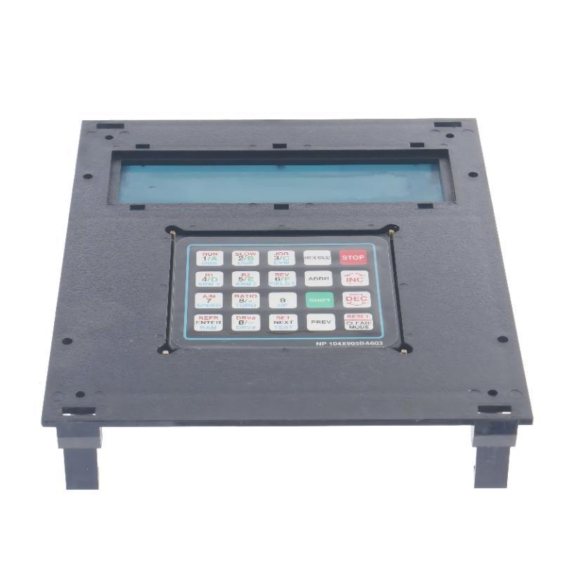
GE 104X905BA603 Fault Diagnosis: Separate Display and Keypad Problems
Start by identifying what still works.
If the display is operating normally, the associated control system is at least providing some level of interface power or communication. Concentrate on the keypad circuit and its connection.
If both display and keypad are inactive, investigate the common interface path first.
A useful field diagnostic tree is:
Display active?
→ Yes → Test individual keys
→ No → Check panel supply/interface
→ Both intermittent → Inspect connector and mechanical seating
→ One key permanently active → Inspect membrane/switch circuit
This prevents unnecessary replacement of the complete assembly.
GE 104X905BA603 Keypad Troubleshooting Through Operator Input
Test the keys individually rather than pressing several buttons repeatedly.
Record the result in a simple matrix:
| Test | Observation | Diagnostic Direction |
|---|---|---|
| Key A | No response | Individual key circuit |
| Key B | Normal | Controller/interface likely active |
| Key C | Intermittent | Mechanical or contact issue |
| Several adjacent keys | No response | Key matrix or connection |
| All keys | No response | Common interface path |
The pattern is more valuable than simply reporting “keypad not working.”
If several adjacent keys fail simultaneously, inspect the shared keypad circuit or connector before concluding that multiple individual switches have failed.
GE 104X905BA603 Troubleshooting Case: Stuck Key Input
A useful real-world failure pattern occurs when the display continues operating but the control system behaves as if one operator key is being continuously pressed.
The first suspicion may be the application program. However, if the abnormal command disappears when the keypad assembly is disconnected according to the equipment service procedure, the fault boundary moves toward the physical keypad.
Inspection should then focus on:
Membrane deformation
Contamination around the key
Damaged switch contacts
Connector seating
Cable damage
Moisture or chemical exposure
A keypad should not be replaced solely because one command appears incorrect in software. The input path needs to be isolated first.
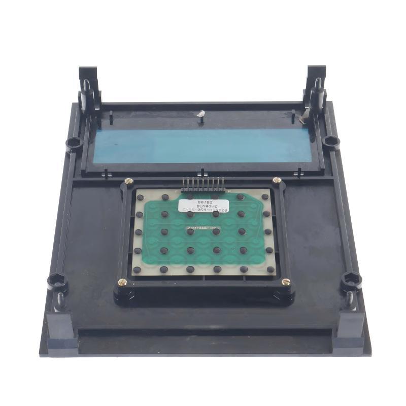
GE 104X905BA603 Display and Keypad Repair Strategy
For an intermittent fault, lightly inspecting the mechanical interface can provide useful diagnostic information, but avoid applying excessive force to the membrane or connector.
If cleaning and reseating do not restore stable operation, compare the suspect panel with a known-good unit where practical.
The 104X905BA603 has been listed as discontinued by the manufacturer in available parts databases, so preservation of working assemblies and careful repair assessment can be important for older installations.
For this reason, component-level Fault Diagnosis should be completed before discarding an otherwise recoverable panel.
GE 104X905BA603 Troubleshooting After Repair
After repair or replacement, do not test only the failed key.
Run the complete operator interface through its normal operating sequence:
Power-up → display check → full keypad test → command verification → repeated operation
Perform repeated key operations rather than a single successful press. Intermittent membrane or connector faults can disappear temporarily and return after vibration or thermal cycling.
The repair should be considered successful only when the display remains stable and all required operator commands are consistently recognized.

