Allen-Bradley MPL-A310P-SJ74AA Servo Motor Installation Guide: Wiring and Commissioning
Time:2026-08-25 Browse: 10
The Allen-Bradley MPL-A310P-SJ74AA servo motor is a low-inertia 230 V AC rotary servo motor with a 100 mm frame, 5000 RPM rated speed, single-turn high-resolution encoder, keyed shaft, right-angle SpeedTEC DIN connector, and 24 V DC brake. Proper mechanical alignment, motor feedback wiring, brake control, and drive configuration are the key points during installation and commissioning.
Allen-Bradley MPL-A310P-SJ74AA Servo Motor Installation Requirements
Before installation, confirm that the motor specification matches the motion application. The MPL-A310P-SJ74AA uses an IEC metric mounting arrangement and has a 100 mm frame size. Its low-inertia construction makes it suitable for applications requiring responsive acceleration and deceleration.
Inspect the motor before mounting. Pay particular attention to the shaft, keyway, mounting flange, connectors, and brake wiring. Do not rotate or couple the motor mechanically if the shaft or coupling shows visible damage.
The installation area should also provide adequate ventilation and protection from excessive contamination, vibration, and mechanical shock.
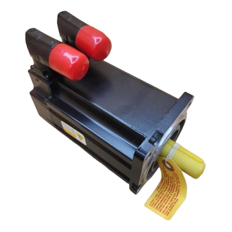
Allen-Bradley MPL-A310P-SJ74AA Servo Motor Mechanical Setup
Correct mechanical alignment is more important than simply tightening the mounting bolts.
Install the motor flange squarely against the machine mounting surface and verify that the driven shaft is properly aligned with the motor shaft. Avoid using the servo motor shaft to compensate for angular or parallel misalignment.
The keyed shaft should be coupled using a compatible hub or coupling. Excessive radial or axial loading can shorten bearing life and create vibration that may later be mistaken for a motor or encoder fault.
The MPL-A310P-SJ74AA is specified with a keyed shaft extension and IEC metric mounting arrangement.
Allen-Bradley MPL-A310P-SJ74AA Servo Motor Wiring and Feedback
The electrical installation should distinguish between motor power, feedback, and brake circuits.
The model uses a right-angle SpeedTEC DIN connector that can be rotated through 180 degrees for cable routing. It also incorporates a 24 V DC brake.
Before energizing the system, verify:
Motor power connections
Encoder/feedback connection
24 V DC brake circuit
Protective grounding
Cable shielding and routing
Connector locking
Drive-to-motor compatibility
Do not assume that a visually similar MP-Series motor uses identical feedback or brake wiring. Confirm the exact model number before making terminal connections.
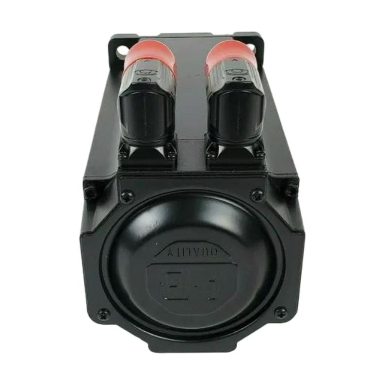
Allen-Bradley MPL-A310P-SJ74AA Servo Motor Setup and Commissioning
Servo Setup should begin with the motor identification and drive configuration. The System Configuration should correspond to the actual MPL-A310P-SJ74AA rather than a similar motor from the same series.
The manufacturer identifies this model as a 5000 RPM motor with a single-turn high-resolution encoder.
During Commissioning, start at low speed and verify the following:
The motor remains stationary when no motion command is present.
The feedback position changes in the expected direction.
The brake releases correctly when commanded.
Motor rotation direction matches the machine axis.
Acceleration and deceleration are stable.
No abnormal mechanical noise or vibration appears.
If the motor immediately faults after enabling, stop the motion test rather than repeatedly resetting the drive.
Allen-Bradley MPL-A310P-SJ74AA Servo Motor Commissioning Field Check
In a representative field commissioning case, a servo axis showed excessive vibration immediately after coupling to the machine. The initial assumption was an incorrect servo tuning value.
The engineer first disconnected the mechanical load and ran the motor at a low test speed. With the load removed, the motor ran smoothly. The vibration returned after the coupling was installed.
A mechanical alignment check then showed that the driven shaft was not properly aligned with the motor shaft. Correcting the coupling alignment reduced the vibration substantially without changing the drive tuning.
This illustrates an important commissioning principle: if vibration changes significantly when the mechanical load is disconnected, investigate the coupling and alignment before modifying servo parameters.
Allen-Bradley MPL-A310P-SJ74AA Servo Motor System Validation
Final validation should cover both electrical and mechanical behavior. Check feedback stability, brake operation, rotation direction, commanded speed, actual speed, and machine positioning.
The motor is specified as a low-inertia servo with a 1.0 in. magnet stack, 100 mm frame size, 5000 RPM speed, and single-turn high-resolution encoder.
A successful Installation Guide process therefore ends with an actual motion test—not simply a powered motor.
Allen-Bradley MPL-A310P-SJ74AA Servo Motor Long-Tail Keywords
This installation article covers long-tail searches including Allen-Bradley MPL-A310P-SJ74AA servo motor installation, MPL-A310P-SJ74AA wiring, MPL-A310P-SJ74AA Setup, MPL-A310P-SJ74AA Commissioning, MPL-A310P-SJ74AA encoder connection, MPL-A310P-SJ74AA brake wiring, and MPL-A310P-SJ74AA servo motor System Configuration.

