GE IS220YAICS1A I/O Analog Module Installation Guide
Time:2026-08-26 Browse: 11
GE IS220YAICS1A installation should begin with module identification, terminal verification, and system configuration before field wiring is energized. As an I/O analog module, the unit must be correctly seated in the control system and matched with the configured I/O channel assignments before commissioning.
GE IS220YAICS1A I/O Analog Module Role
The GE IS220YAICS1A is an I/O analog module used to interface analog field signals with a GE control system. In a typical installation, the module forms the signal path between field instrumentation and the controller, so wiring quality and channel configuration are just as important as the physical installation.
The installation engineer should verify the module part number against the project I/O list before connecting any field conductors. If the cabinet contains similar IS220-series modules, do not rely on appearance alone.
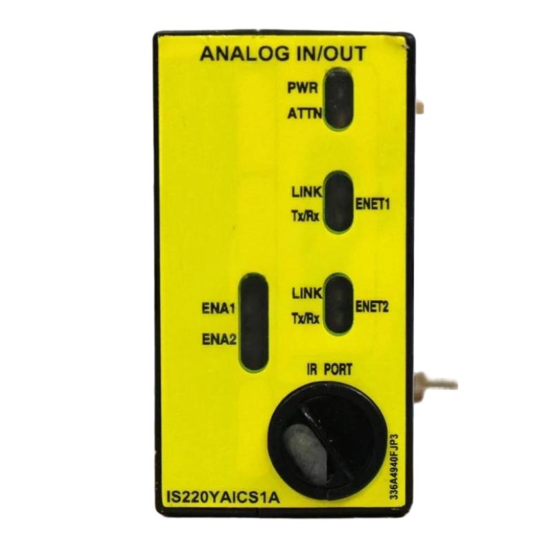
GE IS220YAICS1A Installation Preparation
Before mounting the module, confirm:
GE IS220YAICS1A part number and hardware condition
Correct rack or terminal-board position
Field wiring identification
I/O channel assignment
Required signal type and range
Controller and I/O configuration
Power isolation status
A useful field practice is to compare the physical terminal labels with the electrical drawings before landing wires. This catches channel-offset errors much earlier than software commissioning does.
GE IS220YAICS1A Analog Module Wiring
Field wiring should be routed according to the project wiring diagram. Keep analog signal wiring separated from high-current power conductors and variable-frequency-drive cables wherever practical.
Before energizing the circuit, check each channel for:
Correct polarity
Continuity
Shield termination
Unwanted shorts to ground
Correct field-device identification
Do not assume that a signal appearing on the correct terminal is automatically assigned to the correct engineering channel. The physical wiring and the System Configuration must agree.
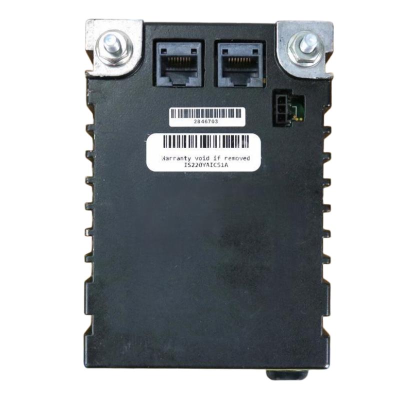
GE IS220YAICS1A System Configuration and Setup
After physical installation, configure the I/O channel assignments in the associated control-system software. Verify that the configured signal type corresponds to the actual field instrument.
For commissioning, compare the raw input value with the expected field condition rather than checking only whether the channel is marked healthy. A stable but incorrect value can indicate a wiring or scaling problem.
GE IS220YAICS1A Commissioning Validation
A practical commissioning check is to introduce a known field signal and compare three values:
Field source → IS220YAICS1A input → controller engineering value
If the source is known to be 50% of its configured range, the controller should show a corresponding value after scaling. Any significant mismatch should trigger signal-path diagnostics before the module is replaced.
In one commissioning case, an analog channel remained near its low limit even though the field transmitter was operating normally. The initial suspicion was a failed I/O module. A point-to-point wiring check instead found that the signal return had been landed on the wrong terminal. After correcting the wiring, the channel tracked the transmitter normally.
GE IS220YAICS1A Installation Fault Checks
If a newly installed channel does not respond, use a logical isolation sequence:
Field device → field wiring → terminal connection → IS220YAICS1A channel → controller configuration
This approach is more reliable than replacing the module immediately.
Check the measured field signal first. If the correct signal reaches the module but the controller value remains incorrect, move the investigation toward channel configuration or module hardware. If the field signal itself is absent, module replacement is premature.
GE IS220YAICS1A Installation Long-Tail Keywords
Common search terms associated with this Installation Guide include:
GE IS220YAICS1A installation guide
GE IS220YAICS1A I/O analog module setup
GE IS220YAICS1A wiring guide
GE IS220YAICS1A commissioning procedure
GE IS220YAICS1A analog input configuration
GE IS220YAICS1A System Configuration
GE IS220YAICS1A I/O module installation

