Allen-Bradley MPL-A320P-SJ74AA Servo Motor Installation Guide
Time:2026-08-27 Browse: 11
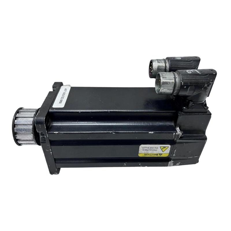
The Allen-Bradley MPL-A320P-SJ74AA is a 230/240 V AC low-inertia servo motor designed for high-speed motion applications, with a 100 mm frame, 50.8 mm magnet stack, 5000 RPM rated speed, single-turn high-resolution encoder feedback, and a 24 V DC holding brake. For reliable installation, the motor should be treated as part of a complete motion system rather than as an isolated Servo Motor.
MPL-A320P-SJ74AA Installation Preparation
Before mounting the motor, verify that the selected servo drive, feedback interface, motor power cable, and brake circuit are compatible with the MPL-A320P-SJ74AA.
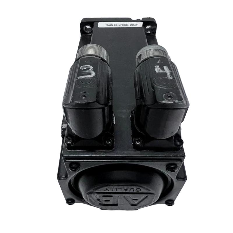
The motor uses a right-angle SpeedTEC DIN connector that can be rotated through 180°, which is useful when cable direction is restricted inside a machine enclosure. The standard configuration also includes a keyed shaft and 24 V DC brake.
Before applying power, check:
Motor nameplate and catalog number
Servo drive motor selection
Power and feedback cable identification
Brake wiring
Shaft and coupling alignment
Mounting flange condition
Protective grounding
Cable routing and connector seating
A common commissioning mistake is to complete the mechanical installation first and only then discover that the feedback or brake configuration does not match the drive.
MPL-A320P-SJ74AA Mechanical Installation
The 100 mm frame motor should be mounted on a rigid, accurately aligned machine surface. Do not use the motor shaft or connector body as a means of positioning the motor.
When installing a coupling, avoid forcing the coupling onto the keyed shaft with excessive impact. Radial or axial loading beyond the application limits can create vibration that may later be misdiagnosed as an encoder or bearing problem.
After mounting, rotate the machine mechanically where possible and check for abnormal resistance before enabling the servo drive.
For applications requiring shaft sealing or a higher environmental protection arrangement, verify the exact motor configuration rather than assuming that all MPL variants have identical enclosure characteristics.
MPL-A320P-SJ74AA Servo Motor Wiring
The electrical installation has three critical paths:
Servo power → Motor
Feedback → Drive
24 V DC brake → Brake circuit
The MPL-A320P-SJ74AA uses a high-resolution single-turn encoder and a SpeedTEC DIN connector. A loose feedback connector can produce symptoms that resemble a defective encoder, so connector locking should be checked before attempting Fault Diagnosis.
Keep motor power wiring physically separated from sensitive feedback wiring where the cabinet layout permits. Avoid unnecessary parallel routing with contactor, inverter, or high-current motor cables.
MPL-A320P-SJ74AA Setup and Drive Configuration
The servo drive must be configured for the correct motor data before motion is enabled.
Confirm the configured:
Motor catalog number
Motor voltage class
Feedback type
Encoder resolution or feedback identification
Rated speed
Brake operation
Direction of rotation
Motor thermal parameters where applicable
The MPL-A320P-SJ74AA is specified at 5000 RPM and approximately 3.05 N·m rated torque, with a listed peak torque of approximately 7.91 N·m. These values should be used as application reference data rather than as a reason to operate continuously at the peak torque level.
MPL-A320P-SJ74AA Commissioning Procedure
The first Commissioning test should be performed with the machine in a controlled and unloaded condition whenever the application allows it.
Enable the drive and observe:
Servo-ready status
Feedback recognition
Brake release
Actual motor position
Actual velocity
Motor current
Drive fault status
Command a low-speed movement first. Confirm that commanded direction and actual direction agree.
If the drive reports a feedback fault immediately after enable, do not continue increasing the command speed. First inspect the feedback connector, cable continuity, drive configuration, and encoder identification.
MPL-A320P-SJ74AA Installation Validation
A useful field validation is to compare commanded and actual motion at several speeds rather than testing only one movement.
For example, during a commissioning check, the motor can be observed at 10%, 25%, and 50% of the intended operating speed. Watch for excessive following error, abnormal current, mechanical noise, or unstable velocity.
If the motor runs smoothly at low speed but develops increasing vibration with speed, investigate alignment, coupling balance, mechanical resonance, and feedback behavior before assuming that the motor itself has failed.
MPL-A320P-SJ74AA Servo Motor Installation Long-Tail Keywords
This Installation Guide is relevant to searches for Allen-Bradley MPL-A320P-SJ74AA servo motor installation, MPL-A320P-SJ74AA wiring, MPL-A320P-SJ74AA setup, MPL-A320P-SJ74AA commissioning, Allen-Bradley MPL servo motor configuration, MPL-A320P-SJ74AA encoder setup, and 24 V DC brake wiring for MPL-A320P-SJ74AA.

