Allen-Bradley MPL-A320P-SJ74AA Servo Motor Troubleshooting Guide
Time:2026-08-27 Browse: 14
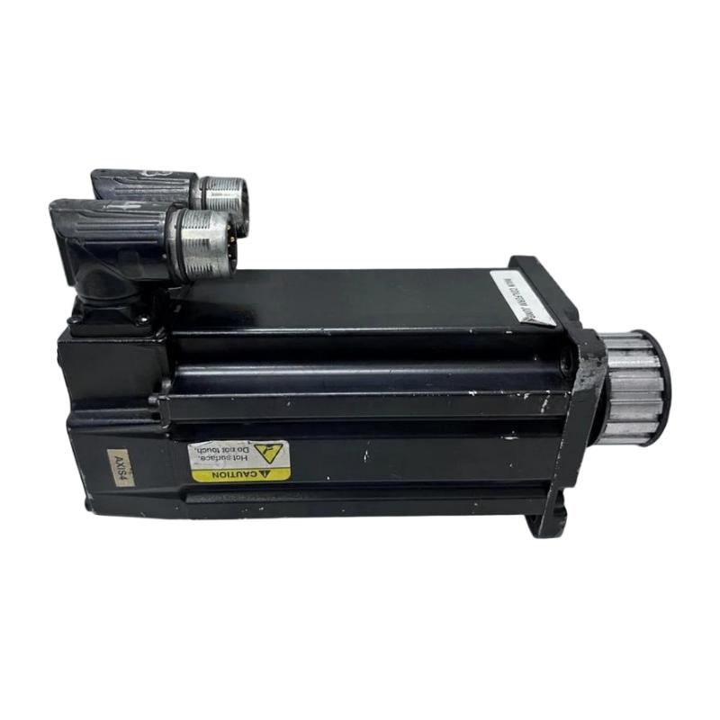
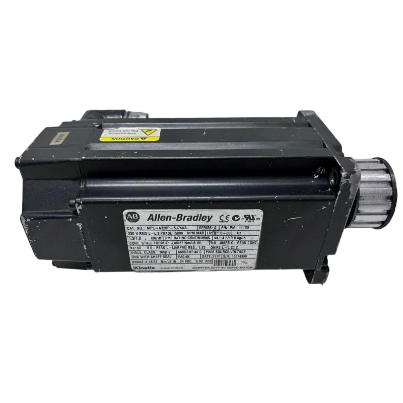
When an Allen-Bradley MPL-A320P-SJ74AA refuses to enable, loses position, or produces a feedback-related drive fault, the motor should not be replaced immediately. The faster Fault Diagnosis method is to determine whether the problem follows the encoder signal, brake circuit, motor power circuit, or mechanical load. The MPL-A320P-SJ74AA uses a single-turn high-resolution encoder and a 24 V DC brake, making feedback and brake circuits two important diagnostic points.
MPL-A320P-SJ74AA Servo Motor Fault Symptoms
A field technician may encounter one of several different symptoms:
Drive reports a feedback or encoder fault during enable.
Motor does not rotate although the drive indicates a command is present.
Motor moves briefly and then faults.
Servo axis shows excessive following error.
Motor hums but does not accelerate normally.
Brake does not release.
Position becomes unstable after several operating cycles.
These symptoms can have very different causes even when they appear under the same general "servo motor fault" category.
MPL-A320P-SJ74AA Feedback Fault Diagnosis
Start with the timing of the fault.
If the fault appears immediately when Servo Enable is commanded, check feedback recognition first. Inspect the SpeedTEC DIN connector and feedback cable for incomplete insertion, damaged contacts, contamination, or mechanical strain.
If the drive recognizes the encoder at startup but loses feedback only while the motor is moving, pay closer attention to cable movement.
A useful diagnostic test is to monitor the feedback status while slowly moving the motor through its normal travel. If feedback disappears only when the cable bends or vibrates, the cable or connector becomes a stronger suspect than the encoder itself.
This distinction matters because replacing the motor will not correct an intermittent feedback cable.
MPL-A320P-SJ74AA Brake Fault Investigation
The 24 V DC holding brake is another possible source of a "motor will not move" condition.
A practical diagnostic sequence is:
Enable command → Brake release command → Brake voltage → Mechanical release → Motor torque
If the drive commands brake release but the expected 24 V DC signal is absent, investigate the brake output, relay, wiring, or control logic.
If 24 V DC is present but the brake remains mechanically engaged, the problem may be within the brake mechanism rather than the servo amplifier.
Do not increase motor torque simply to overcome a brake that has not been confirmed as released. Doing so can create unnecessary motor current and mechanical stress.
MPL-A320P-SJ74AA Servo Motor Real-World Fault Case
In one typical commissioning-style failure, a servo axis reported a feedback fault only after several minutes of operation. Initial static testing showed that the encoder was recognized correctly, so the motor was not immediately condemned.
The technician then monitored the feedback status while moving the axis repeatedly. The fault appeared when the motor cable reached a particular bend position.
The diagnostic conclusion changed from "possible encoder failure" to "intermittent feedback connection."
After the connector and cable routing were corrected, the axis completed repeated motion cycles without losing feedback.
The important engineering clue was the relationship between the fault and physical cable movement. A single successful power-up test would not have exposed this problem.
MPL-A320P-SJ74AA Motor Running but Position Is Unstable
If the motor runs but position regulation is poor, separate the electrical and mechanical causes.
Check the drive's actual position and velocity feedback first. If the feedback signal is stable but following error remains high, inspect:
Mechanical coupling
Backlash
Excessive load
Shaft alignment
Acceleration and deceleration settings
Motion profile
Servo tuning
Mechanical resonance
The MPL-A320P-SJ74AA is a low-inertia motor with a 5000 RPM rated speed, so application dynamics can be important when the motor is coupled to a high-inertia machine load.
A useful diagnostic comparison is motor current versus following error. High current with relatively small commanded movement can indicate excessive mechanical resistance, while unstable feedback with otherwise normal mechanical behavior points the investigation toward the feedback path.
MPL-A320P-SJ74AA Troubleshooting Decision Tree
A practical Fault Diagnosis sequence can be reduced to four questions:
Does the drive recognize the feedback?
If no, inspect the encoder cable, connector, configuration, and feedback circuit.
Does the brake release?
If no, verify the 24 V DC brake circuit and mechanical brake operation.
Does the motor receive the expected power command?
If no, investigate drive enable conditions, limits, alarms, and configuration.
Does the motor move but fail to follow the command?
If yes, investigate mechanical load, coupling, tuning, resonance, and feedback quality.
This approach prevents unrelated faults from being grouped together as a single "servo motor problem."
MPL-A320P-SJ74AA Repair and Recovery Verification
After correcting the fault, repeat the operating condition that originally produced it.
For a feedback fault, perform repeated starts and movements while monitoring encoder status. For a brake fault, verify release and holding behavior several times rather than checking the brake only once. For a following-error problem, test the axis at progressively higher acceleration and speed.
Record the drive fault code, feedback status, motor current, commanded speed, actual speed, and mechanical condition before closing the repair.
MPL-A320P-SJ74AA Servo Motor Troubleshooting Long-Tail Keywords
This Troubleshooting Guide covers Allen-Bradley MPL-A320P-SJ74AA fault diagnosis, MPL-A320P-SJ74AA servo motor feedback fault, MPL-A320P-SJ74AA encoder troubleshooting, MPL-A320P-SJ74AA brake fault, Allen-Bradley servo motor repair, MPL-A320P-SJ74AA position error troubleshooting, and MPL-A320P-SJ74AA servo commissioning faults.

