Allen Bradley MPL-B310P-HJ72AA Servo Motor Installation Guide
Time:2026-09-02 Browse: 15
Allen Bradley MPL-B310P-HJ72AA servo motor installation should focus on correct mechanical mounting, motor feedback connections, grounding, and drive configuration before commissioning. A proper setup reduces encoder faults, excessive vibration, unexpected motion, and commissioning delays.
Allen Bradley MPL-B310P-HJ72AA Servo Motor Installation Preparation
Before installing the MPL-B310P-HJ72AA, inspect the motor housing, shaft, connector area, and mounting surface for signs of shipping damage. Confirm that the motor specification matches the application and that the compatible Allen Bradley servo drive and feedback system have been selected.
The mounting surface should be rigid and accurately aligned. Avoid using the motor shaft to compensate for mechanical misalignment. Coupling errors can create radial or axial loading that may later appear as a motor fault.
Check the following before installation:
Motor model and nameplate information
Mounting dimensions
Shaft and coupling compatibility
Servo drive compatibility
Feedback and power cable condition
Protective grounding
Machine travel limits and mechanical stops
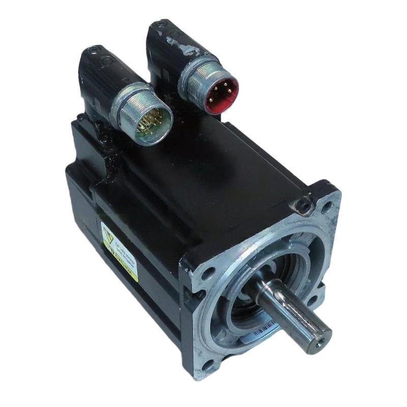
Allen Bradley MPL-B310P-HJ72AA Servo Motor Mechanical Setup
The MPL-B310P-HJ72AA should be mounted on a stable machine structure with the shaft properly aligned to the driven mechanism. Couplings should be installed according to the coupling manufacturer's requirements.
During setup, rotate the mechanism manually where permitted. Look for binding, uneven resistance, or mechanical interference before applying servo power.
This is an important field check because a motor that runs normally without a load can show excessive current or following error once connected to a poorly aligned mechanism.
Allen Bradley MPL-B310P-HJ72AA Wiring and Feedback Installation
Power, feedback, and grounding connections must be made according to the applicable Allen Bradley documentation for the complete motion-control system.
Inspect connectors carefully before mating them. A connector that appears mechanically installed may still have an incomplete electrical connection.
Keep motor power cables separated from sensitive feedback wiring where practical. Check shielding and grounding arrangements carefully, especially in cabinets containing variable-frequency drives, contactors, and other high-energy switching equipment.
Never connect or disconnect motor wiring while the drive is energized.
Allen Bradley MPL-B310P-HJ72AA Servo Drive Configuration
The servo drive configuration should match the actual MPL-B310P-HJ72AA motor rather than relying on a similar motor model.
Verify the motor identification, feedback configuration, direction, scaling, limits, and applicable motion parameters. If the system uses an Allen Bradley PLC Controller, also confirm that the PLC program and motion-axis configuration correspond to the installed motor and drive.
System Configuration errors can produce symptoms that look like hardware failures. For example, an incorrect motor selection can cause abnormal current behavior or prevent successful axis commissioning even when the motor itself is electrically healthy.
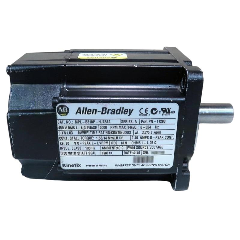
Allen Bradley MPL-B310P-HJ72AA Commissioning Checks
During commissioning, begin with low-risk motion and verify the axis response before allowing the machine to operate at normal speed.
Observe:
Motor direction
Acceleration and deceleration
Actual versus commanded position
Following error
Motor current
Feedback stability
Mechanical vibration
Drive diagnostic status
In one commissioning case, an axis produced noticeable vibration during low-speed movement. The initial assumption was a servo tuning issue. Mechanical inspection showed that the coupling alignment was slightly off. After correcting the alignment, the vibration decreased substantially without replacing the servo motor or drive.
This type of engineering judgment is useful during Setup and Commissioning: always distinguish between an electrical control problem and a mechanical problem before changing servo parameters.
Allen Bradley MPL-B310P-HJ72AA Installation Validation
A completed installation should leave a clear baseline for future Troubleshooting. Record the initial drive configuration, normal operating current, feedback behavior, positioning accuracy, and any relevant machine parameters.
If a fault develops later, these baseline values make Fault Diagnosis considerably faster because the engineer can compare the present condition with a known-good operating state.
Allen Bradley MPL-B310P-HJ72AA Installation Long-Tail Keywords
This Installation Guide covers long-tail searches including Allen Bradley MPL-B310P-HJ72AA servo motor installation, MPL-B310P-HJ72AA servo motor setup, Allen Bradley MPL-B310P-HJ72AA commissioning, MPL-B310P-HJ72AA wiring, MPL-B310P-HJ72AA System Configuration, and Allen Bradley servo motor commissioning guide.

