Honeywell FS-IOBUS-HBS I/O Bus Module Installation Guide (System Setup & Commissioning)
Time:2026-09-14 Browse: 0
Honeywell FS-IOBUS-HBS installation should be treated as an I/O bus architecture task rather than a simple Module replacement. The unit is used as a horizontal I/O bus backplane within the Honeywell Safety Manager I/O system, so correct chassis compatibility, connector seating, bus alignment, and System Configuration are more important than simply mounting the hardware.
Honeywell FS-IOBUS-HBS I/O Bus Module Role
The FS-IOBUS-HBS provides the horizontal I/O bus connection within the associated Safety Manager I/O chassis. It forms part of the internal communication path between the chassis backplane and installed I/O hardware.
For engineers performing an Installation Guide procedure, the first task is to identify the complete chassis arrangement. The FS-IOBUS-HBS should not be approached like a standalone PLC Controller, analog Module, or field Sensor. Its performance depends on the surrounding I/O architecture.
This is particularly important when replacing an existing unit because an apparently identical mechanical installation may still produce communication problems if the chassis configuration is incorrect.
FS-IOBUS-HBS Installation Preparation
Before installation, isolate the equipment according to the plant's approved electrical safety procedure.
Inspect the FS-IOBUS-HBS for mechanical damage, contamination, bent contacts, cracked connectors, or loose mounting points. Compare the replacement unit with the removed assembly before installation.
The following checks are useful during preparation:
Confirm the exact FS-IOBUS-HBS part number.
Verify the target Safety Manager chassis configuration.
Check the associated I/O backplane and extender arrangement.
Confirm that the mounting position is correct.
Inspect connectors and mating surfaces.
Record existing diagnostic conditions before maintenance.
Recording the original diagnostic state is especially useful when the replacement is being performed because of an intermittent communication fault.
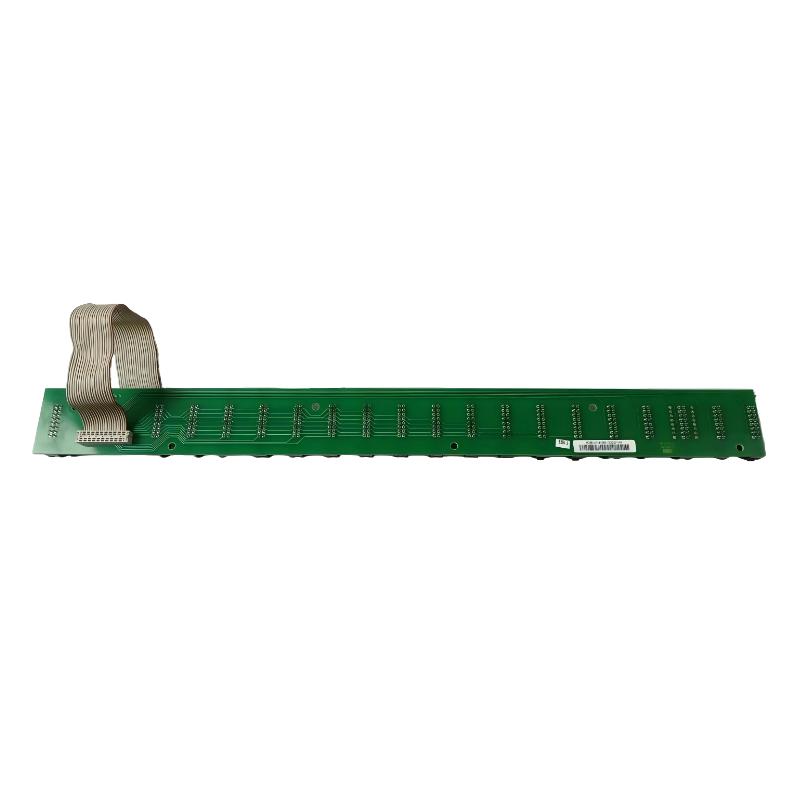
Honeywell FS-IOBUS-HBS Mechanical Setup
The FS-IOBUS-HBS should be positioned carefully within the designated chassis assembly. The bus connection must align naturally with its mating hardware.
Do not force the assembly into position. Excessive mechanical pressure can damage connectors and may create intermittent electrical contact that is difficult to diagnose later.
After positioning the bus assembly, check that the associated hardware is seated evenly and that no connector is partially engaged.
From a field-engineering perspective, this is one of the most important parts of the Setup procedure. A bus assembly that looks mechanically installed can still have a marginal connection.
FS-IOBUS-HBS Wiring and Interface Checks
Unlike a conventional field I/O Module, the FS-IOBUS-HBS is associated with the internal I/O bus rather than direct process wiring.
The installation inspection should therefore concentrate on the bus interface and chassis connections.
Check for:
Correct connector engagement
Clean mating surfaces
Correct backplane alignment
Secure mechanical fastening
Correct I/O module positioning
Correct installation of associated bus hardware
If several I/O modules will communicate through the same bus section, verify their physical arrangement against the approved System Configuration before energizing the system.
Honeywell FS-IOBUS-HBS System Configuration
Hardware installation should be followed by a configuration review.
Confirm that the physical I/O arrangement corresponds with the engineering configuration. Pay particular attention to module positions and the expected chassis architecture.
A common commissioning mistake is to confirm that the controller starts and then assume that the I/O system is correctly configured. Successful startup alone does not prove that every bus connection is functioning correctly.
The better approach is to compare:
Configured hardware → Physical hardware → Diagnostic status → I/O communication
Any mismatch should be investigated before proceeding with process commissioning.
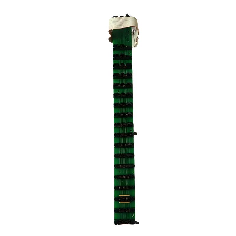
FS-IOBUS-HBS Setup and Commissioning Validation
After the mechanical installation and configuration checks are complete, energize the system according to the approved commissioning procedure.
Observe the controller and I/O diagnostics during startup. Verify that the expected I/O hardware is recognized and that no new bus-related diagnostic condition appears.
During Commissioning, record useful observations such as:
I/O module recognition status
Bus communication status
Chassis diagnostic indications
Unexpected module alarms
Startup behavior
Changes after correcting connections
The objective is not simply to prove that the FS-IOBUS-HBS is powered. The objective is to establish that the complete I/O communication path is stable.
Honeywell FS-IOBUS-HBS Installation Case
In one commissioning case, several unrelated I/O points became abnormal immediately after work had been performed inside the I/O cabinet.
The first assumption was that individual I/O modules had failed. However, the affected points were distributed across different field devices, making simultaneous field-device failure unlikely.
The engineer traced the common path from the affected modules toward the chassis bus. A physical inspection identified an improperly seated bus connection.
After the connection was corrected, the I/O diagnostics returned to normal without replacing the individual modules.
The useful engineering lesson was that the number and grouping of affected channels can be more informative than the alarm description itself.
FS-IOBUS-HBS Installation Validation Checklist
Before returning the Safety Manager system to normal service, verify:
FS-IOBUS-HBS is mechanically secure.
Associated connectors are fully seated.
The I/O chassis arrangement matches the System Configuration.
Expected I/O modules are correctly recognized.
No unexpected bus diagnostic remains active.
Process I/O has been functionally checked.
Maintenance observations have been recorded.
A proper Installation Guide should end with functional validation rather than stopping after the hardware has been mounted.
Long-Tail Keywords for Honeywell FS-IOBUS-HBS Installation
Honeywell FS-IOBUS-HBS Installation Guide, Honeywell FS-IOBUS-HBS setup, FS-IOBUS-HBS commissioning, Honeywell Safety Manager I/O bus installation, FS-IOBUS-HBS I/O bus backplane installation, Honeywell FS-IOBUS-HBS System Configuration, FS-IOBUS-HBS replacement procedure, Honeywell I/O bus Module installation.

