Honeywell FS-IOBUS-HBS I/O Bus Fault Diagnosis and Troubleshooting Guide
Time:2026-09-14 Browse: 0
Honeywell FS-IOBUS-HBS communication faults should first be investigated at the common bus and chassis level when multiple I/O channels fail together. Because the FS-IOBUS-HBS forms part of the internal I/O communication path, replacing individual I/O Modules without checking the shared bus connection can lead to an incorrect Fault Diagnosis.
Honeywell FS-IOBUS-HBS Fault Symptoms
FS-IOBUS-HBS-related problems may appear as unusual I/O communication behavior rather than a simple hardware failure message.
Useful symptoms to record include:
Several I/O channels becoming abnormal simultaneously
Multiple modules showing communication-related diagnostics
An I/O section intermittently disappearing
Communication recovering after cabinet intervention
Repeated I/O bus alarms after system restart
Different field devices reporting abnormal status at approximately the same time
The timing and distribution of the fault are important.
For example, one failed Sensor normally leads the engineer toward the field device or individual I/O Module. Several unrelated Sensors and signals failing together suggest a shared communication path instead.
FS-IOBUS-HBS Fault Diagnosis Strategy
A practical Troubleshooting approach is to work from the affected signals toward their common hardware.
Start with the field signal and establish whether the process device is still behaving normally. Then examine the individual I/O Module diagnostics. If several modules are affected together, move the investigation upstream toward the chassis and I/O bus.
The diagnostic path can be expressed as:
Field signal → I/O Module → I/O backplane → FS-IOBUS-HBS → controller-side diagnostics
This prevents unnecessary replacement of healthy modules.
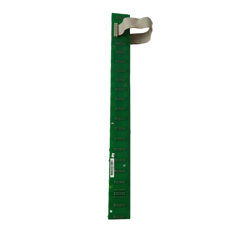
Honeywell FS-IOBUS-HBS Communication Fault Investigation
Suppose four unrelated process signals become unavailable within a few seconds.
Rather than immediately replacing four I/O modules, compare their physical locations and communication path.
If the affected modules share the same bus section, the probability of a common bus-related problem becomes much higher.
At this point, inspect:
Bus connections
Connector seating
Chassis alignment
Backplane condition
Evidence of mechanical disturbance
Recent maintenance activity
The key engineering question is:
What do all failed channels have in common?
That question often narrows the Fault Diagnosis faster than repeatedly resetting the controller.
FS-IOBUS-HBS Intermittent Fault Troubleshooting
Intermittent faults require a different approach because the system may be normal when maintenance personnel arrive.
Record when the fault occurs and whether it correlates with:
Startup
Cabinet maintenance
I/O module replacement
Mechanical movement
Temperature changes
Power cycling
Process disturbances
If a communication fault disappears after reseating hardware, treat this as evidence of a possible connection problem rather than immediate proof of a defective Module.
A temporary recovery after physical movement is especially valuable diagnostic information.
Honeywell FS-IOBUS-HBS Physical Fault Diagnosis
Before replacing the FS-IOBUS-HBS, inspect the physical assembly carefully.
Look for damaged contacts, contamination, loose mechanical hardware, connector deformation, or signs that the assembly has been disturbed during previous maintenance.
The inspection should also include the mating components. A healthy bus assembly cannot compensate for a damaged or poorly aligned connection elsewhere in the chassis.
When troubleshooting a Safety Manager system, always consider the surrounding architecture instead of isolating the suspected component too early.
FS-IOBUS-HBS Troubleshooting Case: Common-Path Failure
In one field troubleshooting case, multiple I/O points showed abnormal status while the corresponding process instruments continued to produce reasonable values.
The initial suspicion was an I/O Module failure. However, signal analysis showed that the affected points were not connected to the same type of field instrument.
The engineer then mapped the affected points against the chassis arrangement. The common factor was their shared I/O bus path.
After the chassis and bus connections were inspected, a marginal connection was identified. Correcting the connection restored communication, and no individual I/O module required replacement.
This type of failure demonstrates why channel correlation is a powerful Fault Diagnosis tool.
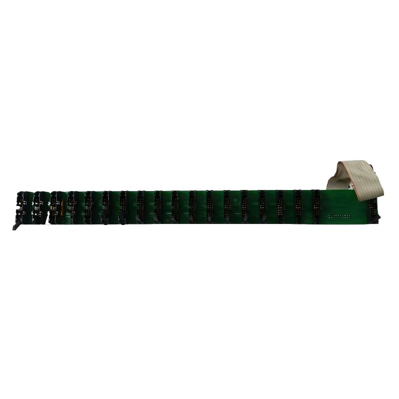
Honeywell FS-IOBUS-HBS Repair Decision
The FS-IOBUS-HBS should not be replaced solely because an I/O communication alarm is present.
Replacement becomes more appropriate when the following conditions have been established:
The chassis System Configuration is correct.
Associated I/O modules have been checked.
External field causes have been eliminated.
Physical connections are confirmed to be correct.
The same bus-related fault repeatedly returns.
Evidence points specifically toward the bus assembly.
This diagnostic sequence separates a genuine FS-IOBUS-HBS hardware problem from a connection or configuration problem.
FS-IOBUS-HBS Recovery and Commissioning
After repair or replacement, repeat the relevant Setup and Commissioning checks.
Confirm that the previously affected I/O modules are correctly recognized and that the original diagnostic condition does not return.
For an intermittent fault, a single successful restart is not sufficient evidence of recovery. The system should be observed under representative operating conditions and compared with the original fault behavior.
A useful maintenance record is:
Fault condition → Diagnostic evidence → Corrective action → Restart → I/O validation → Stable operation
This creates a much stronger technical record than simply stating that the module was replaced.
Honeywell FS-IOBUS-HBS Troubleshooting Decision Logic
When investigating a suspected FS-IOBUS-HBS problem, use the failure pattern to guide the next test.
Single I/O channel abnormal: investigate the field device and individual I/O Module.
Several unrelated channels abnormal: identify their common communication path.
Multiple modules in one bus section abnormal: inspect the I/O bus and chassis connections.
Fault appears after cabinet maintenance: check mechanical seating and connector alignment.
Fault disappears temporarily after physical intervention: investigate intermittent contact before replacing electronics.
Fault persists after configuration and connection checks: evaluate FS-IOBUS-HBS replacement.
This approach reduces unnecessary hardware replacement and makes Troubleshooting more evidence-based.
Long-Tail Keywords for Honeywell FS-IOBUS-HBS Troubleshooting
Honeywell FS-IOBUS-HBS Troubleshooting Guide, Honeywell FS-IOBUS-HBS Fault Diagnosis, FS-IOBUS-HBS communication fault, Honeywell Safety Manager I/O bus troubleshooting, FS-IOBUS-HBS repair, FS-IOBUS-HBS replacement, Honeywell horizontal I/O bus backplane fault, FS-IOBUS-HBS communication troubleshooting, Honeywell I/O bus Module fault diagnosis.

