ABB 5STP24L2800 Thyristor Module Installation Guide (Setup & Commissioning)
Time:2026-09-15 Browse: 0
ABB 5STP24L2800 thyristor module installation requires careful attention to mechanical mounting, pulse-transformer connections, semiconductor protection, and cooling. In ABB DCS drive systems, the 5STP24L2800 is used as a power thyristor in high-current converter assemblies; ABB documentation identifies it as part of DCS converter configurations rated up to 3200 A, with six devices used in a 2Q arrangement and twelve in a 4Q arrangement.
ABB 5STP24L2800 Thyristor Module Role in the Converter
The ABB 5STP24L2800 is a power thyristor rather than a PLC Controller, conventional I/O Module, or low-voltage switching device. Its job is to control high-power current through controlled semiconductor switching inside the converter power stage.
For ABB DCS installations, the thyristor works together with the pulse-transformer board, power interface board, semiconductor fuses, and forced-air cooling system. ABB service documentation lists the 5STP24L2800 with the DCA0016169P1 code in several DCS converter configurations.
This distinction matters during System Configuration. A correct control signal does not guarantee correct converter operation if the gate circuit, power connections, protection devices, or thermal path are incorrect.
ABB 5STP24L2800 Installation Preparation
Before installation, verify the complete converter assembly rather than checking the thyristor alone.
Confirm:
ABB 5STP24L2800 part number and physical condition
Correct converter type and circuit arrangement
Correct semiconductor fuse specification
Pulse-transformer board compatibility
Power interface board configuration
Cooling fan operation
Busbar arrangement
Mounting hardware and electrical contact surfaces
For the ABB DCSxxx-3200 converter configuration, ABB documentation associates the 5STP24L2800 with the SDCS-PIN-48 pulse-transformer board, SDCS-PIN-51 power interface board, 170M7034 semiconductor fuses, and RG35P-4DK.7M.1R / RG35P-4DK.7M.1L cooling fans.
Do not substitute components simply because their electrical ratings appear similar. The complete firing and protection arrangement must be considered.
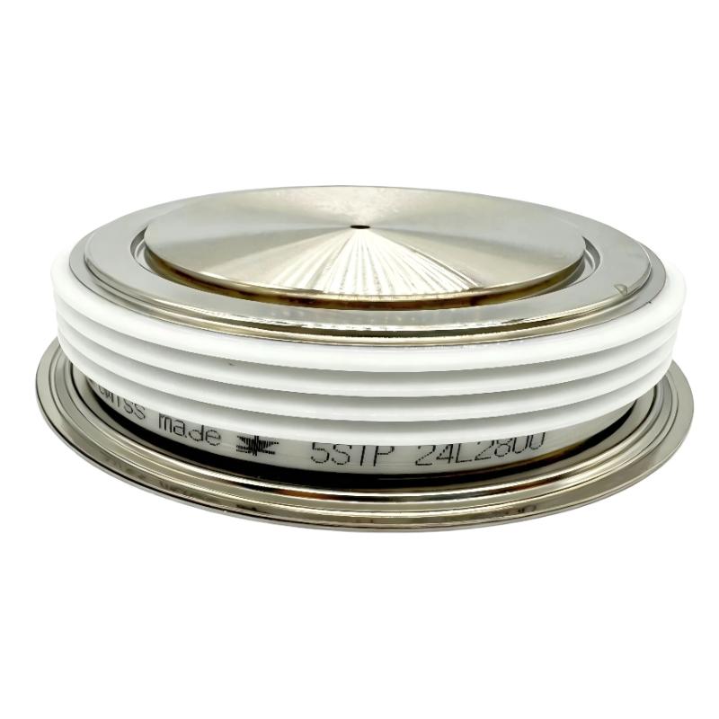
ABB 5STP24L2800 Mechanical Installation and Thermal Contact
The mechanical interface is part of the electrical design. A thyristor carrying high current can develop substantial heat, so poor mounting pressure or contamination between the device and its cooling interface can increase thermal resistance.
Before fastening the device, inspect the contact surfaces for:
Dust or metallic particles
Scratches or raised areas
Oxidation
Uneven contact
Damaged mounting hardware
Install the device according to the converter manufacturer's specified mechanical procedure and tightening requirements. Avoid using excessive force merely to obtain a visually tight connection.
From a field-maintenance perspective, a clean and even thermal interface is more important than simply tightening the hardware as hard as possible.
ABB 5STP24L2800 Power and Gate Connection Checks
The power terminals must be checked against the actual converter drawing before energization. Never rely only on the physical position of a replacement device.
The gate circuit also requires attention. A thyristor may appear electrically healthy during a simple static check while still failing to turn on correctly because of an open pulse-transformer connection or poor gate-circuit continuity.
During the installation check, trace the complete firing path:
Control electronics → pulse-transformer board → gate connection → ABB 5STP24L2800.
This is a more reliable approach than checking the semiconductor in isolation.
ABB 5STP24L2800 Setup and Commissioning Checks
Commissioning should begin with the converter de-energized and mechanically verified.
Check the semiconductor fuses and cooling arrangement first. ABB documentation shows that the converter assemblies using the 5STP24L2800 include dedicated semiconductor fuses and cooling fans.
After the basic inspection:
Verify all power connections.
Verify the firing circuit.
Confirm cooling airflow.
Check control-system configuration.
Apply auxiliary/control power according to the drive procedure.
Confirm that no protection alarm is active.
Perform the manufacturer's recommended firing and current checks.
Increase load gradually while monitoring current and temperature.
The important point is to avoid applying full operating load immediately after a semiconductor replacement.

ABB 5STP24L2800 Commissioning Fault Diagnosis
If the converter does not produce the expected output, begin with the control-to-power relationship.
For example, if the control system requests a firing condition but the corresponding converter current remains near zero, check the gate pulse path before condemning the thyristor.
If current appears immediately when it should not, investigate the firing circuit, device condition, and associated protection components before changing software parameters.
A useful field diagnostic sequence is:
Command present → firing pulse present → gate circuit continuous → semiconductor conducts → output current responds.
Breaking the problem into these five observations prevents unnecessary replacement of expensive power components.
ABB 5STP24L2800 Installation Field Case
In one representative converter commissioning case, the control system was operating normally, but the DC output remained significantly below the expected value after a thyristor replacement. The initial assumption was that the new device was defective.
The diagnostic process instead followed the firing path. The control command was present, but the expected gate-drive response was not reaching the semiconductor correctly. Inspection of the pulse-transformer connection identified a poor connection in the firing circuit.
After correcting the connection and repeating the commissioning test, the converter responded normally.
The lesson is important: when a power thyristor appears not to conduct, Fault Diagnosis should follow the complete gate-drive chain before replacing the semiconductor again.
ABB 5STP24L2800 Long-Tail Installation Keywords
Common search terms associated with this application include ABB 5STP24L2800 Installation Guide, ABB 5STP24L2800 thyristor installation, 5STP24L2800 Setup, 5STP24L2800 Commissioning, ABB DCS thyristor replacement, 5STP24L2800 gate circuit testing, ABB thyristor Module System Configuration, and 5STP24L2800 Fault Diagnosis.
These terms describe different stages of the same engineering task: installing the semiconductor correctly, confirming the firing circuit, and validating converter operation under controlled conditions.

