Allen-Bradley MPL-A560F-SK72AA Servo Motor Installation Guide (Setup & Commissioning)
Time:2026-09-20 Browse: 0
Allen-Bradley MPL-A560F-SK72AA servo motor installation requires correct motor identification, mechanical alignment, 240 V AC power compatibility, feedback configuration, and controlled commissioning. The MPL-A560F-SK72AA is an MP-Series low-inertia brushless servo motor with a 165 mm frame size, 152.4 mm magnet stack, 3000 rpm rated speed, single-turn high-resolution encoder, keyless shaft, right-angle SpeedTEC DIN connector, and no brake. Rockwell Automation lists its country of origin as Mexico.
Allen-Bradley MPL-A560F-SK72AA Servo Motor Installation Requirements
Before mounting the Allen-Bradley MPL-A560F-SK72AA, verify the complete motion system rather than treating the servo motor as an isolated component. The motor must be matched with the appropriate servo drive, feedback interface, motor power connection, and mechanical load.
The model identification is particularly important because closely related MPL-A560F variants can have different encoder, shaft, or brake configurations. For example, the MPL-A560F-SK72AA uses a single-turn high-resolution encoder, keyless shaft extension, and no brake.
Before installation, check:
Motor catalog number and nameplate
Servo drive compatibility
240 V AC system requirement
Encoder configuration
Motor power cable and feedback connection
Mechanical coupling
Shaft alignment
Grounding and shielding
Load inertia and allowable operating conditions
Do not substitute a similar-looking MPL motor without checking the complete catalog number.
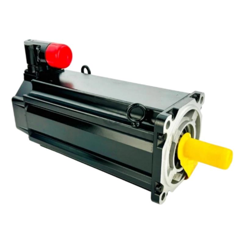
MPL-A560F-SK72AA Servo Motor Mechanical Mounting
The MPL-A560F-SK72AA uses a 165 mm frame and 152.4 mm stack length. Its IEC metric mounting arrangement should be matched to the machine's mounting plate and coupling arrangement.
The mechanical installation should begin with the motor flange and mounting surface. The mounting face should be clean and free from burrs or contamination. If the motor is connected directly to a gearbox, ballscrew, roller, or other driven mechanism, check shaft alignment before applying full operating speed.
A common commissioning mistake is to compensate for mechanical misalignment through servo tuning. This can make the axis appear acceptable at low speed while producing excessive following error, vibration, or current demand at higher speed.
For this reason, mechanical alignment should be verified before aggressive drive tuning.
Allen-Bradley MPL-A560F-SK72AA Wiring and Feedback Setup
The MPL-A560F-SK72AA uses a right-angle SpeedTEC DIN connector and a high-resolution single-turn feedback device.
During Setup, verify the motor power and feedback connections separately. A loose feedback connection can produce a completely different symptom from a motor power problem, so both circuits should be inspected before Fault Diagnosis.
Pay particular attention to:
Servo drive → motor power → encoder feedback → protective grounding
Feedback cable routing should avoid unnecessary proximity to high-current switching conductors. Shielding and grounding should follow the drive manufacturer's wiring requirements.
Before enabling the axis, verify that the drive recognizes the expected motor and feedback configuration. An incorrect motor selection in the System Configuration can produce abnormal current, incorrect feedback interpretation, or commissioning faults even when the physical wiring appears correct.
MPL-A560F-SK72AA Servo Motor Setup and Commissioning
The Setup / Commissioning process should start with the axis unloaded or operated under a controlled mechanical condition whenever the machine design permits.
The initial sequence should focus on:
Motor identification → feedback recognition → low-speed rotation → direction verification → position feedback → load connection → operating-speed validation
At low speed, observe whether the actual motor direction corresponds to the commanded direction. Also compare commanded and actual position. If the motor rotates correctly but the feedback position moves in the wrong direction, stop the commissioning process and investigate the feedback configuration rather than continuing with tuning.
The MPL-A560F family includes versions with different shaft and encoder arrangements, so relying only on the general MPL-A560F family name is insufficient for System Configuration.
Allen-Bradley MPL-A560F-SK72AA Servo Motor Commissioning Data
The MPL-A560F motor family is rated at 3000 rpm, with the MPL-A560F specification showing approximately 5.3 kW rated output, 26.8 Nm continuous stall torque, 61.0 Nm peak stall torque, and 42.0 A continuous stall current.
These figures are useful during commissioning because they provide context when evaluating drive current and load behavior. They should not, however, be treated as a substitute for the exact motor-drive application data.
In one commissioning situation, a servo axis showed noticeably higher current during acceleration than expected. The first assumption was an incorrect drive configuration. After checking the motor parameters, the investigation moved to the mechanical side. The coupling was not properly aligned, increasing the load demand during acceleration. Correcting the alignment reduced the abnormal current response without changing the motor or controller.
This illustrates an important field principle: servo Troubleshooting should separate electrical configuration problems from mechanical problems before changing parameters.
Allen-Bradley MPL-A560F-SK72AA Installation Validation
After successful Setup / Commissioning, operate the axis through several representative movements rather than validating only one jog command.
Record useful baseline information such as:
Motor speed
Drive current
Following error
Position error
Acceleration response
Feedback status
Drive diagnostic status
Mechanical vibration
These measurements create a reference for future Fault Diagnosis.
A properly commissioned Allen-Bradley MPL-A560F-SK72AA should have a documented relationship between its physical installation, drive parameters, feedback configuration, and mechanical load. This makes later Troubleshooting substantially more efficient.
Allen-Bradley MPL-A560F-SK72AA Installation Guide Long-Tail Keywords
Allen-Bradley MPL-A560F-SK72AA Servo Motor Installation Guide, Allen-Bradley MPL-A560F-SK72AA servo motor wiring, MPL-A560F-SK72AA Setup and Commissioning, MPL-A560F-SK72AA servo motor configuration, MPL-A560F-SK72AA feedback setup, MPL-A560F-SK72AA servo commissioning, Allen-Bradley MP-Series servo motor installation.

