Allen-Bradley MPL-A560F-SK72AA Servo Motor Troubleshooting Guide for Excessive Current
Time:2026-09-20 Browse: 0
Allen-Bradley MPL-A560F-SK72AA servo motor excessive-current faults should be diagnosed by separating mechanical load, motor wiring, feedback behavior, and drive configuration. The MPL-A560F family has a 3000 rpm rated speed and approximately 26.8 Nm continuous stall torque, so an axis that suddenly requires substantially more current than its established commissioning baseline deserves investigation rather than immediate motor replacement.
Allen-Bradley MPL-A560F-SK72AA Servo Motor Fault Symptoms
Excessive current can appear in several ways:
Drive overload or overcurrent alarm
High current during acceleration
Motor heating
Abnormal mechanical noise
Position following error
Slow acceleration despite a normal command
Repeated drive trips under load
The timing of the fault provides an important diagnostic clue.
If current rises immediately when the axis is enabled, inspect motor wiring, feedback configuration, and drive parameters first.
If current remains normal at no load but increases sharply after the machine is mechanically engaged, the load, coupling, gearbox, bearings, or driven mechanism becomes more important to investigate.
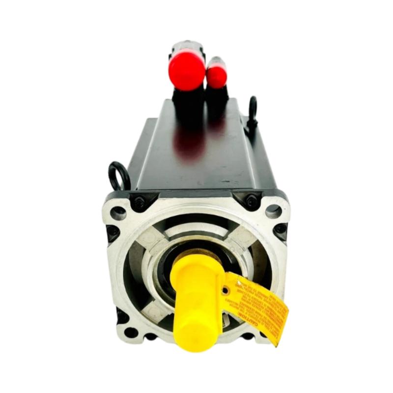
MPL-A560F-SK72AA Fault Diagnosis Through Current Behavior
Do not begin Troubleshooting by changing the servo gain.
Instead, compare three conditions:
Motor disabled → motor enabled without load → motor operating with load
If the drive reports normal behavior with the mechanical load disconnected but excessive current after coupling, the servo motor itself is less likely to be the first suspect.
The MPL-A560F-SK72AA has a relatively substantial 26.8 Nm continuous stall torque rating, so a sudden increase in current during an otherwise unchanged machine cycle can be a useful indicator of a change in the mechanical system.
Check for:
Coupling misalignment
Excessive bearing resistance
Mechanical obstruction
Incorrect gearbox ratio
Increased process load
Shaft binding
Incorrect acceleration settings
Allen-Bradley MPL-A560F-SK72AA Servo Motor Troubleshooting Case
In one field-style diagnostic case, an MPL-A560F-SK72AA axis operated normally during manual jogging but repeatedly generated an overcurrent condition during automatic acceleration.
The initial observation suggested that the acceleration profile might be too aggressive. However, reducing acceleration only delayed the fault.
The next test compared motor current with the machine mechanically isolated. The current response became stable when the driven mechanism was disconnected. This shifted the investigation away from the servo motor and toward the mechanical load.
Inspection found that the driven assembly had developed additional resistance. After the mechanical restriction was corrected, the axis returned to normal acceleration without replacing the motor.
The important Fault Diagnosis point was not the final repair itself. The decisive measurement was the difference between unloaded and loaded current behavior.
MPL-A560F-SK72AA Servo Motor Wiring Fault Diagnosis
Electrical faults should be investigated when excessive current occurs even without the expected mechanical load.
Inspect the motor power circuit for:
Loose terminals
Damaged cable insulation
Incorrect phase connections
Ground faults
Connector damage
Contamination around the SpeedTEC connection
The MPL-A560F-SK72AA uses a right-angle SpeedTEC DIN connector.
Do not assume that a physically connected connector is electrically reliable. During Troubleshooting, inspect the connector condition and cable routing, particularly if the fault is intermittent or appears after machine vibration.
Allen-Bradley MPL-A560F-SK72AA Feedback Fault Diagnosis
The MPL-A560F-SK72AA uses a single-turn high-resolution encoder.
Feedback problems can produce symptoms that resemble mechanical instability. If actual position does not correspond to the commanded movement, check the feedback status before increasing servo gains.
A useful diagnostic comparison is:
Commanded position → Actual position → Following error → Motor current
If the motor current increases while the following error also grows, determine whether the motor is physically being prevented from following the command or whether the feedback information is incorrect.
Changing tuning parameters before resolving an unreliable feedback signal can make the system harder to diagnose.
MPL-A560F-SK72AA Repair and Recovery Strategy
Once the fault source has been isolated, the repair should address the specific failure rather than replacing unrelated components.
For a mechanical fault, correct alignment, binding, or load resistance.
For a wiring fault, repair the cable or connector and repeat insulation and continuity checks according to the applicable maintenance procedure.
For a configuration fault, restore the verified motor and feedback parameters in the System Configuration.
For a confirmed motor fault, compare the motor's electrical and mechanical behavior against the manufacturer's specifications before replacement.
The MPL-A560F-SK72AA is a no-brake configuration, so a replacement decision should not assume that another MPL-A560F motor with a brake or different encoder arrangement is an interchangeable substitute.
Allen-Bradley MPL-A560F-SK72AA Troubleshooting Verification
After Repair, repeat the same operating condition that originally produced the fault. A successful reset of the alarm is not sufficient evidence that the problem has been solved.
Record the new baseline:
Commanded speed → actual speed → current → following error → drive status
For a production machine, compare these values against the original commissioning records whenever available.
The most useful Allen-Bradley MPL-A560F-SK72AA Troubleshooting approach is to reproduce the fault, isolate the electrical and mechanical variables, measure the signal or current at each stage, and only then decide whether the servo motor, drive, wiring, or machine load requires repair.
Allen-Bradley MPL-A560F-SK72AA Troubleshooting Long-Tail Keywords
Allen-Bradley MPL-A560F-SK72AA Troubleshooting Guide, MPL-A560F-SK72AA Fault Diagnosis, MPL-A560F-SK72AA servo motor overcurrent fault, MPL-A560F-SK72AA servo motor repair, Allen-Bradley servo motor excessive current, MPL-A560F-SK72AA feedback troubleshooting, MPL-A560F-SK72AA servo drive fault diagnosis.

