GE 1719-0023 Analog Main Board Installation Guide: Setup and Commissioning
Time:2026-09-22 Browse: 0
GE 1719-0023 installation should focus first on board identification, signal compatibility, wiring condition, and system configuration. When an analog main board is replaced in an operating PLC or industrial control system, incorrect channel assignment or field wiring can cause symptoms that look like hardware failure. A controlled installation and commissioning process helps separate configuration problems from genuine board faults.
GE 1719-0023 Analog Main Board Installation Overview
The GE 1719-0023 is used as an analog control component within an industrial automation system. Its job is closely tied to the controller's analog signal processing and the field devices connected to the system.
Before installation, confirm the complete part number on the existing board and compare it with the replacement unit. This is particularly important when several GE boards have similar physical construction but different electrical functions.
The cabinet should also be inspected before the board is installed. Look for loose terminals, damaged connectors, oxidized contacts, excessive dust, and signs of overheating. A replacement board cannot correct a wiring problem that already exists in the cabinet.
GE 1719-0023 Installation Preparation
The first practical task is to record the condition of the existing installation.
Note the board position, connector locations, associated terminal blocks, channel assignments, and field-device connections. If the system is still operational, record several normal analog values before shutdown. These measurements provide useful reference points during commissioning.
Power should be isolated according to the site's maintenance procedure before the board is removed. The technician should not rely only on the PLC software status to determine whether the hardware is safe to handle.
Pay particular attention to static protection. Analog electronics can be affected by electrostatic discharge even when there is no visible physical damage.
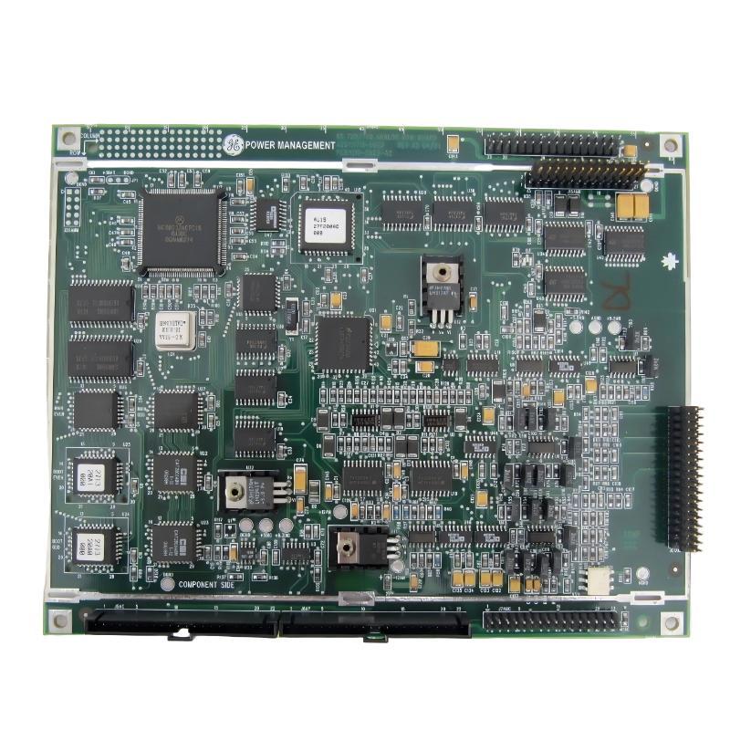
GE 1719-0023 Wiring and Signal Inspection
The wiring inspection should be completed before connecting the replacement board.
Check each associated signal conductor for loose termination, damaged insulation, poor shielding, and incorrect connection. If the board interfaces with current or voltage signals, confirm that the field signal type agrees with the system documentation.
Cable routing is also worth checking. Analog signal cables installed close to variable-frequency drives, motor cables, contactors, or other high-current equipment can pick up electrical interference. In the field, this may appear as an unstable process value even though the analog board itself is functioning normally.
Where shielded cable is used, inspect the shield termination according to the plant's wiring standard rather than assuming that every shield should be grounded at both ends.
GE 1719-0023 System Configuration Before Commissioning
Hardware installation must match the PLC or control-system configuration.
Verify the board position, channel mapping, signal range, scaling parameters, engineering units, and any associated alarm limits. A channel that is mapped to the wrong address can produce a convincing but completely incorrect process value.
For example, a process instrument may represent a pressure range from 0 to 10 bar using a standard analog signal. The controller must interpret the electrical signal using the same range that was defined for the instrument.
If the hardware and software scaling disagree, the measured electrical signal can be correct while the value displayed to the operator is wrong.
This is why System Configuration should be checked before changing control logic.
GE 1719-0023 Analog Main Board Setup
After the physical installation has been completed, energize the system according to the approved commissioning procedure and observe the controller diagnostics.
Check whether the board is recognized correctly. Review any module, channel, or diagnostic indication before allowing the connected process equipment to operate normally.
A useful commissioning method is to verify the analog response at several operating points rather than checking only the normal running value.
For a configured linear signal, check the low end, a middle point, and the high end. The measured electrical signal should correspond with the value expected by the control system.
For example, if a process signal is configured for a 0–10 V range, a command or simulated input around the middle of the engineering range should produce approximately the corresponding midpoint of the electrical signal. The exact values must follow the plant's approved configuration.
GE 1719-0023 Installation Guide: Field Commissioning Experience
In one commissioning situation, an analog channel appeared incorrect immediately after a replacement board was installed. The operator display showed a process value that was substantially different from the value recorded before maintenance.
The initial suspicion was that the replacement board was defective.
The technician instead checked the channel assignment and compared the configuration with the previous installation record. The physical wiring had been connected to the correct terminal, but the software channel assignment did not correspond to the original configuration.
After the channel mapping was corrected, the analog value returned to the expected range without replacing the board.
This type of problem is common enough to justify checking System Configuration before declaring a newly installed analog board defective.
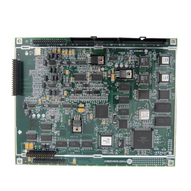
GE 1719-0023 Setup Validation
A proper Setup and Commissioning procedure should finish with independent verification.
Confirm that the board is correctly recognized, all relevant channels respond as expected, the electrical measurements correspond with the configured range, and the connected instruments or actuators respond correctly.
Where possible, compare the value shown in the PLC with a measurement taken directly at the relevant field terminal. Agreement between these two points provides considerably stronger evidence than an HMI value alone.
Also verify that no unexpected alarms, diagnostics, or communication indications appear after the system returns to operation.
GE 1719-0023 Installation Guide Long-Tail Search Terms
This installation guide addresses common search requirements including GE 1719-0023 installation, GE 1719-0023 analog main board installation, GE 1719-0023 wiring, GE 1719-0023 setup, GE 1719-0023 commissioning, GE 1719-0023 System Configuration, and GE 1719-0023 PLC analog signal setup.

