GE 1719-0023 Analog Main Board Troubleshooting Guide: Fault Diagnosis and Repair
Time:2026-09-22 Browse: 0
GE 1719-0023 troubleshooting should begin by determining whether the fault originates in the analog main board, the controller configuration, or the external signal path. An analog channel that remains fixed, drifts unexpectedly, or shows an incorrect process value does not automatically indicate a failed GE 1719-0023. The fastest Fault Diagnosis approach is to compare the controller value with the actual electrical signal at different points in the circuit.
GE 1719-0023 Analog Main Board Fault Symptoms
A GE 1719-0023 fault can appear in several different forms.
The process value may remain unchanged even when the input condition changes. An analog reading may suddenly jump to an abnormal value. One channel may behave differently from other channels. The controller may also display a diagnostic indication while the connected field instrument continues to operate normally.
These symptoms need to be separated before repair work begins.
The first useful question is not "Is the board bad?" It is "Where does the signal stop behaving as expected?"
GE 1719-0023 Fault Diagnosis Begins With Signal Comparison
A practical Troubleshooting process follows the signal from the controller toward the field device.
First check the value inside the PLC or control system. If the software value is already incorrect, measuring the board output may not identify the original cause.
If the controller value is correct, measure the corresponding electrical signal at the board or terminal interface.
If the signal at the board is correct but the field device receives an incorrect value, attention should move toward the wiring, terminal connections, grounding, or receiving equipment.
This simple separation often saves considerable time during field maintenance.
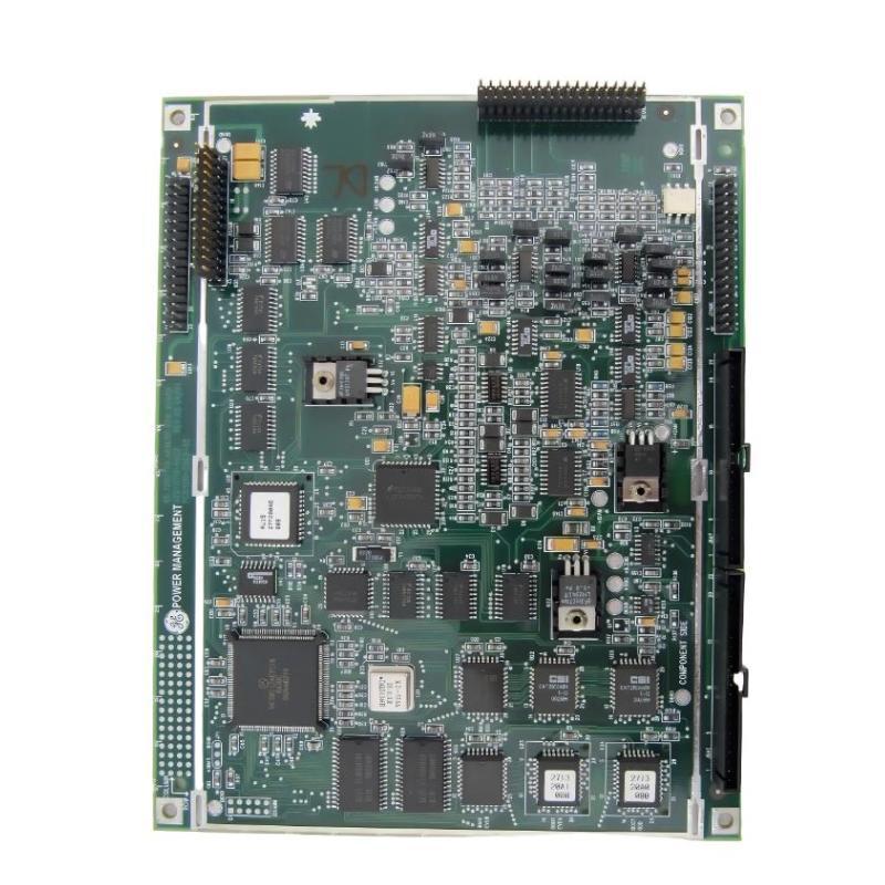
GE 1719-0023 Troubleshooting for an Unresponsive Analog Channel
One useful fault pattern is a channel that does not respond when the process value changes.
For example, a technician may observe that the control-system value changes from approximately 30% to 70%, while the corresponding physical analog signal remains almost unchanged.
The correct response is to verify the controller output first.
If the internal value changes correctly but the measured electrical output remains fixed, inspect the channel configuration and associated wiring. Confirm that the software address corresponds to the physical channel being measured.
If the configuration is correct and neighboring channels operate normally, the board becomes a stronger suspect.
This is more reliable than replacing the board simply because the field device appears unresponsive.
GE 1719-0023 Analog Signal Fault Diagnosis
Analog faults can often be separated by examining whether the signal is stable, fixed, or completely absent.
A completely absent signal suggests a different diagnostic path from a noisy signal.
For an unstable signal, check cable routing, shielding, grounding, terminal tightness, and nearby electrical equipment. Variable-frequency drives and motor circuits are common sources of interference in industrial environments.
For a fixed signal, investigate controller forcing, configuration, channel mapping, and field-device status.
For a completely missing signal, verify the power arrangement, terminal continuity, connector condition, and board diagnostics before deciding that the analog main board requires replacement.
GE 1719-0023 Real Fault Diagnosis Case
In one field troubleshooting case, an operator reported that an analog-controlled process value was fluctuating even though the process itself was relatively stable.
The first measurement showed that the PLC value was moving between approximately 48% and 53%. Because the board was suspected initially, the technician measured the electrical signal directly.
The board output followed the controller value rather than generating an independent fluctuation.
The investigation then moved upstream. The instrument signal feeding the control system was found to be unstable because the signal cable had been routed too close to a high-power motor cable.
After the cable routing and shielding arrangement were corrected, the controller value became stable.
The important Fault Diagnosis point was that the analog board had been responding correctly to an unstable signal. Replacing it would not have solved the problem.
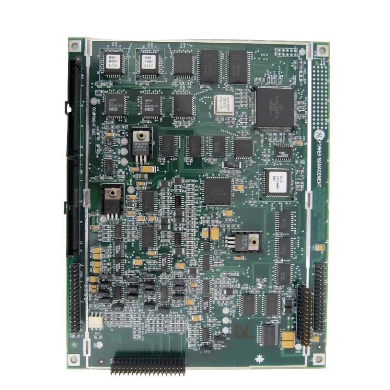
GE 1719-0023 Troubleshooting for Incorrect Scaling
Incorrect scaling can look like a hardware fault when the electrical signal itself is healthy.
Suppose the field instrument is operating over a defined engineering range, but the PLC displays a value that is consistently too high or too low.
Measure the actual signal and compare it with the configured engineering range.
If the electrical measurement is correct but the displayed engineering value is wrong, inspect the scaling parameters rather than replacing the board.
Check the lower range, upper range, engineering units, channel assignment, and any conversion performed in the PLC program.
This type of fault is especially important after a board replacement because configuration files may have been restored incorrectly or a channel may have been assigned to a different position.
GE 1719-0023 Troubleshooting: Distinguishing Board Faults From Wiring Faults
A useful field technique is to compare measurements at two locations.
If the signal is correct at the GE 1719-0023 interface but incorrect at the field terminal, the board is unlikely to be the source of the problem.
If the signal is already incorrect directly at the board while the controller command or expected value is known to be correct, the investigation should focus on the board, its connector, and its immediate configuration.
Loose terminals are particularly easy to overlook. Vibration and thermal cycling can gradually weaken a connection, creating an intermittent fault that disappears when the cabinet door is opened or the wiring is disturbed.
For intermittent problems, record the signal over time rather than relying on a single measurement.
GE 1719-0023 Repair Decision
A GE 1719-0023 repair or replacement decision should be based on evidence collected during Troubleshooting.
Before removing the board, record the channel involved, controller value, measured signal, diagnostic status, and field-device condition.
If configuration and wiring have been verified and the board consistently produces an incorrect or missing signal while the controller is providing a valid command, hardware failure becomes a reasonable conclusion.
After installing a replacement board, repeat the same measurements that identified the original fault. If the replacement produces the expected signal under the same test conditions, the diagnosis is much stronger.
GE 1719-0023 Post-Repair Verification
Repair is not complete simply because the alarm disappears.
Verify the analog signal at the board, confirm the corresponding PLC value, and check the response of the connected field equipment.
Run the system through several representative operating points and watch for drift or intermittent behavior. If the original problem occurred only after the system had been running for several hours, allow sufficient operating time to confirm that the fault has genuinely been eliminated.
Document the measured values and the corrective action. This information can become valuable reference material when a similar fault appears later.
GE 1719-0023 Troubleshooting and Fault Diagnosis Keywords
This guide covers practical search topics including GE 1719-0023 troubleshooting, GE 1719-0023 Fault Diagnosis, GE 1719-0023 analog main board fault, GE 1719-0023 analog signal problem, GE 1719-0023 output troubleshooting, GE 1719-0023 repair, GE 1719-0023 PLC fault diagnosis, and GE 1719-0023 System Configuration troubleshooting.

