GE 531X307LTBAJG1 LAN I/O Terminal Board Installation Guide for Wiring and Commissioning
Time:2026-09-24 Browse: 0
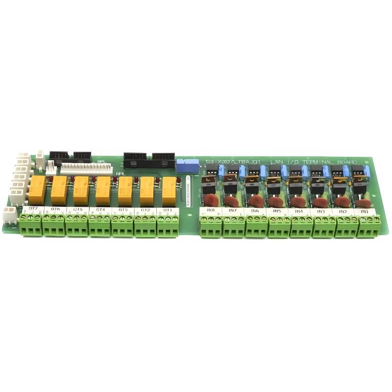
The GE 531X307LTBAJG1 LAN I/O Terminal Board installation should begin with identification of the LTB revision, field wiring, and the associated control hardware rather than simply mounting the board. The board provides an interface between external discrete devices and GE drive or excitation control equipment, with the G1 version supporting eight configurable 24 V DC control-input plugs and seven Form C relay outputs.
GE 531X307LTBAJG1 Installation Role and Signal Path
The 531X307LTBAJG1 belongs to the GE 531X LAN I/O Terminal Board family. In a typical cabinet, the LTB sits between field devices and the control electronics. Pushbuttons, interlocks, contactor feedback, and similar discrete signals are brought into the terminal board, while relay contacts provide low-voltage control outputs.
The important point during installation is to treat the board as a signal interface, not as an independent PLC Controller. Its I/O signals must match the system configuration already defined by the drive or excitation controller.
For the G1 version, the eight configurable input connections are associated with the 8PL interface, which carries I/O information between the LTB and other terminal/control boards.
GE 531X307LTBAJG1 Installation Preparation
Before removing the existing board, record the field wiring and connector positions. A practical commissioning record should include:
Existing terminal numbers
CI1PL through CI8PL connections
IN1 through IN8 signal identification
Relay output assignments
Ribbon-cable orientation
Existing LED status
Power isolation is particularly important in a drive cabinet. Field circuits can remain energized even when the control electronics appear inactive, so voltage should be verified with appropriate test equipment before touching the wiring.
The GE documentation identifies 28–14 AWG wiring for LTB I/O terminals and specifies that a 26-conductor interconnection ribbon cable can be up to 20 ft long. It also warns against routing the I/O ribbon cable together with power wiring because coupling can produce unwanted input behavior.
GE 531X307LTBAJG1 Wiring and System Configuration
The wiring should follow the existing system configuration rather than assigning signals according to physical convenience.
For the eight input channels, check the expected signal voltage and current before connecting an external device. Published GE documentation for the 531X307LTB family identifies input ranges including 24–230 V AC and 24–250 V DC, depending on the input configuration and revision.
A useful field check is:
Field device → LTB input → LTB LED → internal I/O path → controller status
If the field device operates but the corresponding LTB indicator does not change, the problem should be investigated locally before changing the controller configuration.
The seven relay outputs are Form C contacts. They are intended for low-voltage, low-current control functions and can also be used as pilot contacts for external relay arrangements.
GE 531X307LTBAJG1 Setup and Commissioning Checks
After installation, commissioning should be performed one signal at a time.
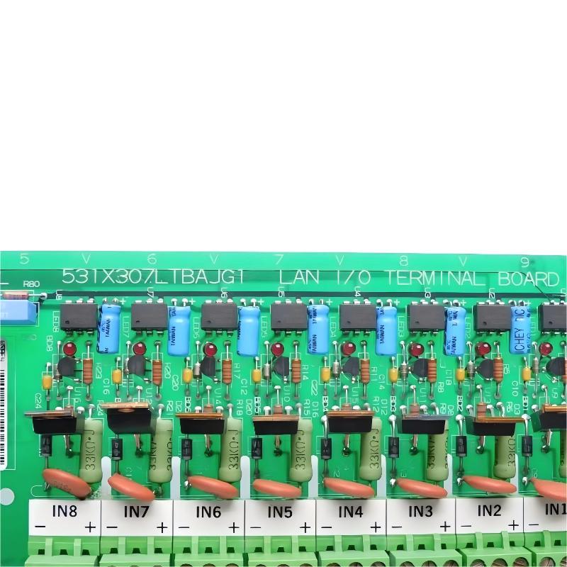
Apply a known input to one channel and observe the corresponding LED. For example, if an external interlock is expected to activate IN3, verify the physical input first and then confirm the associated indication.
Do not assume that an illuminated LED automatically proves the complete signal path. The commissioning check should continue through the internal controller status.
A practical acceptance sequence is:
Input voltage confirmed → LTB LED response confirmed → controller input status confirmed → output/interlock response confirmed
This approach makes it easier to separate a field-wiring problem from a system configuration problem.
GE 531X307LTBAJG1 Installation Validation in a Real Cabinet
In one commissioning situation involving an LTB replacement, the most useful check was not immediately changing the control software. The engineer first photographed the original connector arrangement, transferred each connection individually, and then checked the input indicators against the expected field states.
One input that was expected to remain OFF was found active after wiring. The controller itself was not changed. Measurement at the field terminal showed that the external device was still providing a leakage current sufficient to affect the input circuit.
This type of observation is important with older industrial control systems: a signal that looks logically incorrect at the controller may actually originate from the field circuit.
GE documentation specifically notes that leakage current from devices connected in series with an input can cause an input to remain continuously ON under certain conditions.
GE 531X307LTBAJG1 Setup and Commissioning Long-Tail Keywords
This Installation Guide is relevant to engineers searching for:
GE 531X307LTBAJG1 installation guide, GE 531X307LTBAJG1 wiring, GE 531X307LTBAJG1 setup, GE 531X307LTBAJG1 commissioning, GE 531X307LTBAJG1 LAN I/O Terminal Board installation, GE 531X307LTBAJG1 I/O wiring, GE 531X307LTBAJG1 system configuration, and GE 531X307LTBAJG1 field troubleshooting.
The same diagnostic principle applies when the board is installed as a replacement: verify the physical signal path before modifying controller logic or replacing additional hardware.

