GE 531X307LTBAJG1 I/O Input Fault Troubleshooting and Fault Diagnosis Guide
Time:2026-09-24 Browse: 0
A GE 531X307LTBAJG1 I/O fault should not immediately be treated as a failed terminal board. When an input remains ON, OFF, or behaves intermittently, the more useful Fault Diagnosis method is to compare the field voltage, LTB indicator, and controller status in sequence. The 531X307LTB documentation identifies leakage current, wiring arrangement, and signal coupling as possible causes of abnormal input behavior.
GE 531X307LTBAJG1 I/O Fault Symptoms
A typical fault may appear as an incorrect interlock, an input that refuses to turn OFF, or a controller status that does not correspond with the physical field device.
Common observations include:
IN1–IN8 remains active after the external switch opens
An expected input does not illuminate its indicator
A relay output does not change state
The controller reports an interlock even though the field device appears normal
The fault appears only after another high-power circuit is energized
The signal changes intermittently rather than remaining permanently failed
These symptoms point toward different diagnostic paths.
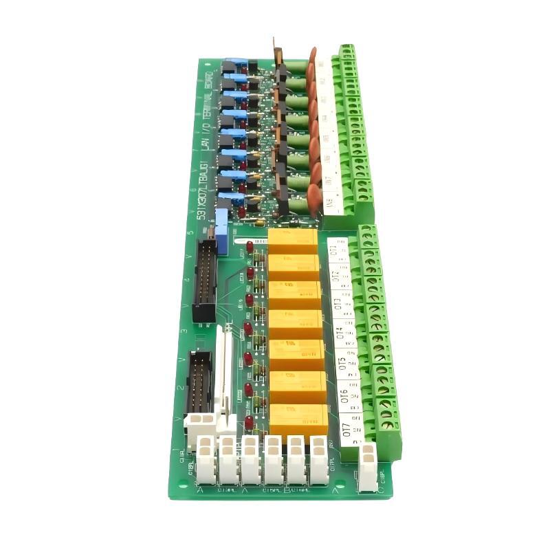
GE 531X307LTBAJG1 Fault Diagnosis Logic
The first question should be:
Is the abnormal state already present at the LTB input, or is it created after the LTB?
This divides the troubleshooting process into two sections.
If the measured field signal is incorrect, investigate the external device, wiring, leakage, or common connection.
If the field signal is correct and the LTB indication does not respond, investigate the terminal board, connector, or associated input circuit.
If the LTB indication is correct but the controller status is wrong, investigate the internal interconnection and system configuration rather than immediately replacing the LTB.
This diagnostic split prevents unnecessary board replacement.
GE 531X307LTBAJG1 Input Stuck ON Investigation
One particularly useful failure pattern is an input that remains ON after its external switch has opened.
The GEH-6005 documentation warns that devices connected in series with an input can cause continuous ON behavior when their leakage current exceeds the applicable threshold. For certain 531X307LTB revisions, the documentation identifies greater than 1.0 mA DC leakage or greater than 4.0 mA peak AC leakage as a condition that can keep an input continuously active.
The field diagnosis therefore begins with measurement rather than board replacement.
Check:
Switch open → voltage/current at LTB input → LED state → controller input state
If the switch is open but measurable current remains in the input circuit, inspect solid-state outputs, indicator circuits, suppression components, and other devices connected in series.
This is a classic case where replacing the PLC Controller or terminal board would not necessarily remove the fault.
GE 531X307LTBAJG1 Communication and Ribbon-Cable Troubleshooting
Another failure pattern occurs when the LTB input indicators respond correctly but the control system does not receive the expected state.
In this situation, inspect the interconnection before modifying the System Configuration.
The 531X307LTB uses a multi-conductor ribbon-cable connection between the terminal board and associated control/terminal hardware. GE documentation specifies a maximum 20 ft length for the 26-conductor interconnection and recommends keeping the I/O ribbon cable away from power wiring.
A practical troubleshooting sequence is:
LTB LED correct → connector seating → cable orientation → cable continuity → controller status
A partially seated connector can produce several apparently unrelated I/O faults at the same time. If several channels fail together, a common connection deserves attention before individual input circuits are suspected.
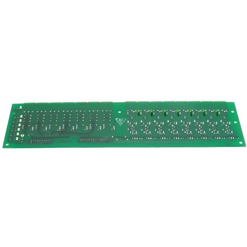
GE 531X307LTBAJG1 Relay Output Fault Diagnosis
If the input side is working but an external actuator does not respond, move the investigation to the relay side.
The LTB provides seven low-voltage, low-current Form C relay contacts. The GE documentation also describes their use as pilot contacts for external high-voltage/high-current relay arrangements.
Measure the relay contact state under the same command that should activate the output.
For example:
Controller command ON → RX indication → relay contact state → external relay coil → final device
If the controller commands the output but the relay indication does not change, suspect the LTB output circuit or its control path.
If the relay changes correctly but the external device does not operate, the fault has moved downstream into field wiring, the external relay, or the actuator circuit.
GE 531X307LTBAJG1 Troubleshooting Case: False Input Activation
In one field-style diagnostic case, an interlock input was reported as permanently active. The first assumption was a defective terminal board because the symptom appeared immediately at the controller.
The engineer instead measured the input circuit with the external switch open.
The field circuit still contained leakage current. After the external interface device was isolated, the LTB input returned to its normal OFF state.
The important engineering conclusion was that the terminal board had been reporting the electrical condition it was receiving. The fault was upstream of the LTB rather than inside the board.
This is why Fault Diagnosis should follow the signal path instead of following the alarm text alone.
GE 531X307LTBAJG1 Repair Decision and Replacement Checks
Replacement becomes more reasonable when the field signal is verified, the wiring is correct, the interconnection is intact, and the LTB channel still fails to respond consistently.
Before installing a replacement 531X307LTBAJG1, record:
Board part number
Revision/suffix
Connector arrangement
Existing input assignments
Relay output assignments
Ribbon-cable routing
LED states before removal
This is especially important because different LTB revisions can have different input arrangements. GE documentation distinguishes G1 and G2 configurations, with the G1 version providing the eight configurable 24 V DC control-input plugs.
GE 531X307LTBAJG1 Troubleshooting Long-Tail Keywords
Engineers searching for this fault condition may use terms such as:
GE 531X307LTBAJG1 troubleshooting, GE 531X307LTBAJG1 fault diagnosis, GE 531X307LTBAJG1 I/O fault, GE 531X307LTBAJG1 input stuck ON, GE 531X307LTBAJG1 relay output failure, GE 531X307LTBAJG1 LAN I/O Terminal Board repair, GE 531X307LTBAJG1 wiring fault, GE 531X307LTBAJG1 signal troubleshooting, and GE 531X307LTBAJG1 System Configuration fault.
For field troubleshooting, the most reliable order remains field signal → terminal-board indication → interconnection → controller status → output circuit. That sequence provides a much stronger Fault Diagnosis path than replacing boards based only on the alarm description.

