ABB V18345-1020520001 Valve Positioner Troubleshooting Guide (Fault Diagnosis)
Time:2026-09-28 Browse: 0
ABB V18345-1020520001 troubleshooting should begin by separating electrical, pneumatic, mechanical, and feedback faults. When a control valve stops responding, replacing the ABB valve positioner immediately is often premature. The TZIDC positioner receives a 4–20 mA command and controls a pneumatic actuator, so a fault anywhere between the controller, loop wiring, positioner, actuator, or valve mechanism can produce similar symptoms.
ABB V18345-1020520001 Valve Positioner Failure Symptoms
One common failure pattern is simple:
The PLC or DCS command changes, but the valve does not move.
The first useful measurements are not internal electronics tests. Measure the actual loop current at the field device and check the pneumatic supply.
For example, assume the control system displays a 16.0 mA command. If the technician measures only 4.1 mA at the positioner terminals, the troubleshooting direction is completely different from a case where 15.9 mA is measured correctly at the field device.
In the first case, investigate the control loop.
In the second case, investigate the positioner, pneumatic system, actuator, or mechanical linkage.
This simple separation can prevent unnecessary replacement of a functioning positioner.
ABB V18345-1020520001 Fault Diagnosis Through the Control Loop
A reliable Fault Diagnosis process follows the signal path rather than the equipment nameplate.
Start at the PLC or DCS output.
Then verify the field current.
After that, inspect the pneumatic response.
Finally, check actuator movement and feedback.
If the PLC output changes from 4 mA to 20 mA but the field current remains fixed at approximately 4 mA, the positioner itself should not yet be considered the primary suspect.
Check the output card, wiring, terminals, isolator, safety barrier, and loop continuity.
The TZIDC family is designed for 4–20 mA two-wire operation, making actual loop-current measurement one of the most useful first-line diagnostic tests.
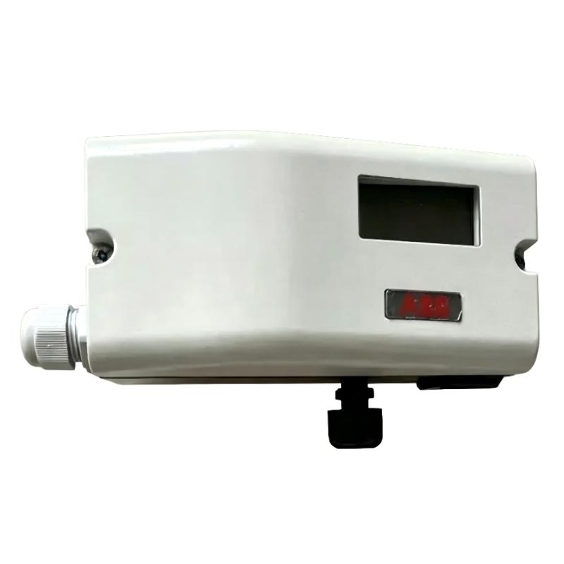
ABB V18345-1020520001 Pneumatic Fault Troubleshooting
A different failure occurs when the electrical signal is correct but the actuator remains stationary.
Suppose the measured input is 15.8 mA and the instrument supply is within the required operating range, but there is no meaningful valve movement.
The investigation should move to the pneumatic side.
Check the instrument-air isolation valve first. Then inspect the regulator, filter, tubing, fittings, and actuator.
The TZIDC operating documentation identifies a supply-air range of 1.4–6 bar (20–90 psi) for the relevant system design.
Do not simply increase the air pressure because the valve is slow. The actuator and complete valve assembly must be operated within their specified limits.
A practical test is to monitor whether pneumatic output changes when the command changes.
If the positioner changes pneumatic output but the actuator does not move, investigate actuator friction, diaphragm or piston condition, valve stem resistance, and mechanical obstruction.
If there is no appropriate pneumatic response despite a stable input signal, the positioner becomes a stronger diagnostic candidate.
ABB V18345-1020520001 Position Feedback Fault Diagnosis
Another common fault has the opposite symptom: the valve moves, but the reported position is wrong.
For example, the actuator physically reaches approximately half travel while the position feedback indicates only a small percentage of movement.
This situation should trigger a mechanical feedback inspection before electronic replacement.
Check the feedback lever, shaft coupling, mounting bracket, and actuator travel.
Look for looseness or slippage that may have developed after valve maintenance.
A positioner can continue receiving a perfectly correct 4–20 mA signal while reporting incorrect travel if the mechanical feedback relationship has changed.
This is why an Installation Guide and a Troubleshooting Guide should never treat calibration as purely a software procedure.
ABB V18345-1020520001 Valve Hunting Troubleshooting
A more subtle fault is continuous valve hunting around the commanded position.
Imagine a stable command corresponding to approximately 50% travel while the actual valve repeatedly moves between roughly 47% and 53%.
The first diagnostic question is whether the command itself is stable.
If the PLC output is also oscillating, investigate the process-control loop.
If the command remains stable while the valve position oscillates, investigate the positioner, actuator, pneumatic supply, and mechanical friction.
Do not immediately alter several tuning parameters at once.
Make one controlled change, observe the response, and record the result. This approach gives the maintenance team a traceable Fault Diagnosis process instead of a trial-and-error adjustment.
ABB V18345-1020520001 HART Communication Fault
A HART communication problem should be treated separately from a basic valve-positioning problem.
A positioner may continue to respond correctly to its 4–20 mA command even when digital communication with the maintenance workstation is unavailable.
When this happens, verify that the installed V18345 configuration actually includes the HART communication option. ABB's TZIDC ordering information distinguishes standard 4–20 mA input from configurations incorporating an FSK module for HART communication.
Next inspect loop conditions, communication connections, barriers or isolators, and the field communicator configuration.
If analog control remains stable while only digital communication is lost, avoid treating the symptom as a complete positioner failure.
The two functions should be diagnosed independently.
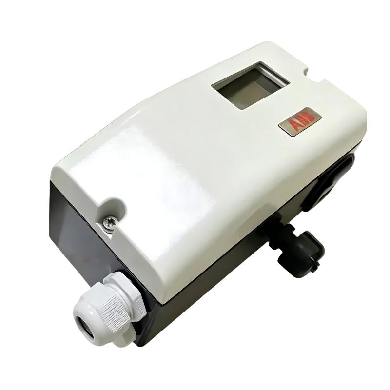
ABB V18345-1020520001 Calibration Fault After Valve Maintenance
Consider a practical maintenance case.
A control valve operates normally before shutdown. During maintenance, the actuator is removed and reinstalled. After startup, the valve responds to the command but the travel indication is no longer correct.
The initial temptation is to suspect an electronic fault.
A better diagnostic sequence is to compare the pre-maintenance and post-maintenance mechanical conditions.
Check the feedback linkage.
Check the actuator mounting.
Check the valve travel.
Then repeat the appropriate Setup and automatic adjustment procedure.
If the positioner operates correctly after the mechanical relationship is restored, replacing the electronics would have addressed the wrong problem.
This pattern is particularly important in plants where valve maintenance occurs frequently because feedback alignment can be disturbed without any visible damage to the positioner itself.
ABB V18345-1020520001 Repair Decision Based on Evidence
Repair or replacement should come after the external causes have been eliminated.
A useful decision chain is:
Control signal verified → field loop verified → pneumatic supply verified → actuator verified → feedback mechanism verified → configuration verified → positioner diagnostics evaluated
If all external conditions are normal and the V18345-1020520001 still fails to generate the expected positioning response, further inspection of the positioner is justified.
ABB's TZIDC documentation describes the V18345 family as an intelligent configurable positioner with local operation and automatic adjustment. The platform also has variants with different communication, feedback, mounting, and protection configurations, so the exact ordering code should be checked before selecting replacement hardware.
This is especially important because two V18345 units may look similar while having different options or electrical configurations.
ABB V18345-1020520001 System Configuration Recovery
After a fault has been corrected, do not stop when the valve begins moving again.
The final recovery should verify the entire control chain.
Change the command gradually through the operating range and confirm that the valve follows it consistently.
Check the feedback value at the same time.
Where HART or another supported communication function is installed, confirm that the device can be identified and diagnostic information can be accessed.
Also verify that no active diagnostic condition remains after the mechanical or pneumatic correction.
A successful recovery means the original failure mechanism has been addressed and the valve has returned to predictable operation—not simply that the actuator moved once.
ABB V18345-1020520001 Troubleshooting Long-Tail Keywords
ABB V18345-1020520001 troubleshooting
ABB V18345-1020520001 fault diagnosis
ABB V18345 valve positioner not responding
ABB V18345 valve position feedback fault
ABB V18345 TZIDC troubleshooting
ABB V18345 4–20 mA fault
ABB V18345 HART communication troubleshooting
ABB V18345 valve hunting fault
ABB V18345 actuator positioning problem
ABB V18345 positioner calibration troubleshooting
ABB TZIDC pneumatic fault diagnosis

