ABB V18345-1020520001 Valve Positioner Installation Guide (Setup & Commissioning)
Time:2026-09-28 Browse: 0
ABB V18345-1020520001 installation starts with correct actuator mounting, feedback alignment, pneumatic connections, and 4–20 mA loop verification. This model belongs to ABB’s V18345/TZIDC intelligent electro-pneumatic positioner family, designed for positioning pneumatically operated linear or rotary actuators. The TZIDC platform supports 4–20 mA two-wire operation, local configuration, automatic adjustment, and optional HART communication depending on the ordered configuration.
ABB V18345-1020520001 Valve Positioner Installation Preparation
Before beginning the ABB V18345-1020520001 Installation Guide procedure, verify the complete valve assembly rather than treating the positioner as an isolated instrument.
The first checks should cover the actuator type, valve travel, mounting bracket, feedback mechanism, instrument-air supply, electrical loop, and area classification. ABB specifies the TZIDC for mounting on linear and part-turn actuators, with mounting arrangements based on applicable actuator standards such as NAMUR and VDI/VDE 3845.
A useful field rule is to move the actuator manually before connecting the control signal. The feedback shaft or lever should move smoothly across the complete travel range. If the mechanism becomes tight near either end, correct the mechanical problem first.
This is important because an incorrectly installed feedback mechanism can make a healthy positioner appear to have a calibration fault.
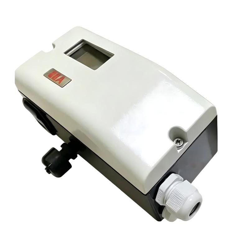
ABB V18345-1020520001 Mechanical Setup and Feedback Alignment
The mechanical Setup determines how accurately the ABB V18345-1020520001 can interpret valve movement.
Secure the positioner to the actuator using the appropriate mounting arrangement and make sure the feedback linkage is firmly connected. Check the full actuator stroke slowly from the minimum to maximum position.
During this inspection, pay particular attention to three conditions:
The feedback linkage should not contact the housing.
The linkage should not become excessively loose at either end of travel.
The actuator should reach its intended mechanical travel without forcing the positioner mechanism beyond its usable range.
In one commissioning case involving a digital valve positioner, the initial automatic adjustment produced an apparently abnormal travel result. The electrical signal was stable, but the feedback mechanism was not correctly aligned with the actuator stroke. Correcting the mechanical alignment before repeating the calibration eliminated the abnormal response.
The engineering lesson is straightforward: do not use electronic parameters to compensate for poor mechanical installation.
ABB V18345-1020520001 Pneumatic Connection Setup
The ABB V18345-1020520001 uses pneumatic output to position the actuator. The TZIDC documentation identifies an instrument-air supply range of approximately 1.4 to 6 bar (20 to 90 psi) for the relevant configuration.
Before connecting the pneumatic tubing, inspect the air supply for contamination, moisture, and pressure instability. Check the filter/regulator and make sure the isolation valve is fully open.
After connecting the tubing, apply instrument air gradually and listen for leakage around fittings.
A small leak can create a surprisingly large positioning problem. For example, if the valve reaches the commanded position slowly and then drifts away after the control signal becomes stable, the technician should not immediately modify the positioner's tuning parameters. Air leakage, actuator friction, or unstable supply pressure may be responsible.
ABB V18345-1020520001 4–20 mA Wiring and Electrical Check
The electrical part of the ABB V18345-1020520001 Installation Guide should be completed only after the mechanical and pneumatic installation has been checked.
The TZIDC platform uses 4–20 mA two-wire technology. ABB documentation specifies a rated input of up to 30 V DC for the applicable V18345 configuration.
Verify the actual field wiring rather than relying solely on the PLC or DCS display.
A practical commissioning measurement sequence is:
Measure the loop voltage at the control cabinet.
Measure the current in the actual field loop.
Confirm polarity at the positioner.
Check the cable termination.
Verify any barrier, isolator, or interface installed between the controller and positioner.
For a nominal 12 mA command, the field instrument should actually receive the corresponding control signal. If the DCS indicates 12 mA but the measured field current is substantially different, investigate the loop before changing the positioner's configuration.
ABB V18345-1020520001 Setup and Automatic Adjustment
Once the mechanical installation and pneumatic connections are confirmed, the ABB V18345-1020520001 Setup can proceed.
The TZIDC design provides local operation and automatic adjustment, allowing the positioner to determine relevant operating characteristics during commissioning.
Automatic adjustment should be treated as a commissioning procedure rather than a substitute for engineering checks.
Observe the actuator while the adjustment routine is running. The valve should move through its expected operating range without mechanical obstruction or abnormal pneumatic behavior.
If the actuator stops unexpectedly, repeatedly oscillates, or reaches a mechanical limit prematurely, stop and investigate the physical installation.
Repeatedly restarting automatic adjustment without identifying the underlying cause can make Fault Diagnosis more difficult.
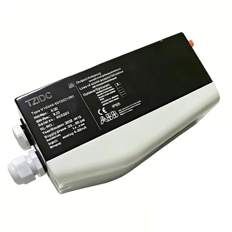
ABB V18345-1020520001 Commissioning and Travel Validation
The most useful ABB V18345-1020520001 Commissioning test is a controlled travel check.
Start from the configured minimum signal and gradually increase the command. Observe the valve position, actuator movement, and positioner feedback simultaneously.
A mid-range command is particularly useful because it reveals whether the positioner has a consistent relationship between input signal and mechanical travel.
For example, if a valve responds normally at the low end but reaches its mechanical stop before the expected maximum command, check the configured travel and feedback alignment before changing the PLC output range.
The final validation should confirm:
Correct electrical signal response.
Stable pneumatic movement.
Correct travel direction.
Correct minimum and maximum position.
Stable valve position after the command stops changing.
Correct system feedback where an optional analog or digital feedback module is installed.
ABB V18345-1020520001 System Configuration Verification
System Configuration should be checked at both the field device and the control-system level.
Confirm the configured input range, actuator direction, fail position, travel parameters, and any optional feedback or communication functions installed on the particular unit.
HART communication is available on applicable TZIDC configurations through the FSK communication option.
For hazardous-area installations, use the exact certification and wiring requirements applicable to the installed version. ABB documentation specifically states that the local communication interface must not be used in a hazardous location.
This distinction matters during field commissioning because a service connection that is acceptable in a workshop may not be permissible in the installed hazardous area.
ABB V18345-1020520001 Installation Guide Field Checklist
Before handing the valve assembly back to operations, record the commissioning baseline.
Record the V18345-1020520001 identification, actuator type, pneumatic supply, input signal, configured travel, feedback response, and communication status.
It is also useful to record the behavior at several signal points instead of recording only the final calibration result.
If a future maintenance technician sees that the valve previously responded normally at low, mid, and high command positions, Troubleshooting becomes much faster.
This commissioning record effectively becomes the reference point for future Fault Diagnosis.
ABB V18345-1020520001 Installation Guide Long-Tail Keywords
ABB V18345-1020520001 installation guide
ABB V18345-1020520001 valve positioner setup
ABB V18345-1020520001 commissioning
ABB V18345 valve positioner wiring
ABB V18345 TZIDC installation
ABB V18345 valve positioner calibration
ABB V18345 4–20 mA setup
ABB V18345 HART configuration
ABB V18345 actuator feedback setup
ABB TZIDC System Configuration

