ABB V18345-2010521001 Valve Positioner Installation Guide (Setup & Commissioning)
Time:2026-09-29 Browse: 0
ABB V18345-2010521001 installation is primarily a matter of correct actuator mounting, pneumatic connection, 4–20 mA loop wiring, and accurate position feedback calibration. This TZIDC electro-pneumatic positioner is configured for a 4–20 mA two-wire input, double-acting actuator service with fail-freeze behavior, and an analog 4–20 mA position-feedback option.
ABB V18345-2010521001 Valve Positioner Installation Requirements
Before beginning the Installation Guide procedure, confirm the complete ordering configuration against the nameplate. The V18345-2010521001 version is associated with the ABB TZIDC family and uses an aluminum housing with a mechanical position indicator. Its specified connections include a 1/2-14 NPT cable entry and 1/4-18 NPT pneumatic connection. The documented configuration has a nominal weight of approximately 1.7 kg.
The mechanical installation should match the actuator type rather than simply following the physical orientation of an existing positioner. ABB TZIDC positioners support linear actuators according to DIN/IEC 534 / NAMUR arrangements and rotary actuator mounting according to VDI/VDE 3845.
Before mounting, check:
Actuator travel and direction
Feedback lever or coupling movement
Positioner mounting bracket rigidity
Pneumatic tubing condition
Supply-air quality
4–20 mA control-loop polarity
Available space for local operation
Correct positioner configuration for the actuator
A loose feedback connection can produce a commissioning problem that looks like an electronic fault. For that reason, mechanical inspection should be completed before changing software parameters.
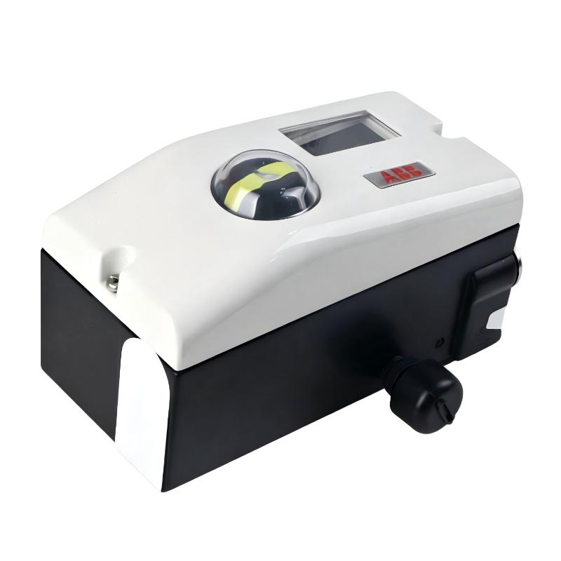
ABB V18345-2010521001 Mechanical Setup and Feedback Alignment
The feedback mechanism is the first part of the Setup that should be checked after the positioner is mounted.
Move the valve through its expected operating range manually, where the actuator design permits safe manual movement. Observe whether the positioner feedback mechanism follows the actuator smoothly. There should not be a sudden change in resistance near either end of travel.
The important engineering question is not simply whether the valve moves. It is whether the positioner can measure the complete travel without reaching a mechanical limit prematurely.
For example, if a valve has a nominal 50 mm actuator stroke but the feedback linkage effectively uses only part of the available measuring range, the positioner may still complete an automatic adjustment while producing poor control resolution around part of the stroke.
Correct the mechanical linkage before attempting electronic calibration.
ABB V18345-2010521001 Pneumatic Connection and Air Supply
The V18345-2010521001 configuration uses pneumatic connections with 1/4-18 NPT air-pipe threading. The documented TZIDC configuration can provide output pressure up to 90 psi in the referenced certification data.
The pneumatic side should be treated as part of the control system, not merely as an air connection.
Check the following before commissioning:
Instrument air is clean and dry.
Tubing is correctly connected to the actuator ports.
Pneumatic fittings do not leak.
Tubing is not excessively long or restricted.
Actuator supply pressure is adequate for the required valve force.
Double-acting actuator connections correspond to the configured fail position.
A useful field check is to isolate the control signal temporarily and observe actuator behavior while verifying the pneumatic circuit. If the actuator cannot hold a stable position because of an air leak, calibration data can become misleading.
ABB V18345-2010521001 4–20 mA Loop Wiring
The electrical input for this configuration is a two-wire 4–20 mA signal. The ABB TZIDC documentation identifies the positioner as a 4–20 mA two-wire device.
The control loop should be checked from the controller output through the field cable and into the positioner terminals.
At minimum, verify:
Correct loop polarity.
No accidental short circuit.
Correct cable shielding practice for the installation environment.
Stable loop current.
Correct DCS/PLC analog-output configuration.
No unexpected resistance in series with the loop.
A useful commissioning measurement is to compare the commanded signal with the actual measured current.
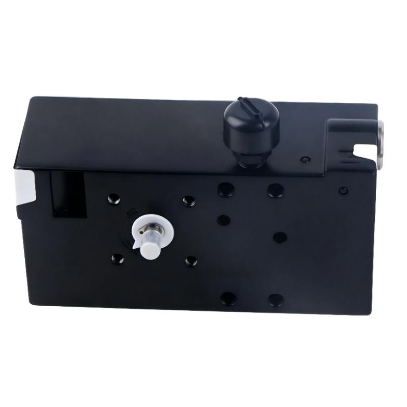
ABB V18345-2010521001 Setup and Commissioning Logic
The most reliable Setup / Commissioning sequence is to establish the mechanical and pneumatic conditions first and then allow the positioner to determine the relationship between command and valve travel.
During commissioning, monitor three variables together:
Input command → Positioner response → Actual valve travel
If the input changes from 12 mA to 16 mA but the valve barely moves, do not immediately conclude that the electronics have failed. Check actuator pressure, linkage movement, valve friction, and configuration first.
The TZIDC family supports local operation and automatic adjustment functions intended to simplify commissioning.
After automatic adjustment, verify the valve at several intermediate points rather than checking only 0% and 100%.
A practical validation sequence is:
0% → 25% → 50% → 75% → 100% → 50% → 25%
The return direction is important because mechanical friction can produce different behavior during opening and closing.
ABB V18345-2010521001 System Configuration Validation
After the positioner has completed its Setup, validate the complete System Configuration from the control room.
The DCS or PLC should display a position that corresponds reasonably with the local valve indication. If an analog feedback option is installed, compare the feedback signal against the actual valve position.
For example, if the valve is physically at approximately 50% travel while the feedback loop reports a value corresponding to 82%, the problem should be investigated at the feedback mechanism and scaling level before the positioner is replaced.
The ABB TZIDC documentation also identifies optional analog position feedback and digital communication variants within the product family, so the exact installed configuration should always be checked against the device ordering code.
ABB V18345-2010521001 Commissioning Fault Prevention
Many commissioning failures originate outside the positioner.
Three common examples are:
Mechanical problem: feedback linkage installed with insufficient travel.
Pneumatic problem: actuator supply pressure falls when the valve starts moving.
Electrical problem: the controller produces the wrong current because of incorrect analog-output scaling.
These faults can produce similar symptoms: unstable travel, incomplete stroke, slow response, or failure of automatic adjustment.
The correct engineering approach is therefore to separate the system into three sections:
Electrical command → Positioner → Pneumatic actuator/valve
Testing each section independently usually takes less time than repeatedly recalibrating the complete system.
ABB V18345-2010521001 Long-Tail Installation Keywords
Common long-tail searches associated with this application include:
ABB V18345-2010521001 Installation Guide
ABB V18345-2010521001 valve positioner setup
ABB V18345-2010521001 commissioning procedure
ABB V18345-2010521001 4–20 mA wiring
ABB TZIDC valve positioner installation
ABB V18345 valve positioner actuator setup
ABB V18345-2010521001 System Configuration
ABB TZIDC electro-pneumatic positioner commissioning
These terms are most useful when connected to actual engineering tasks such as wiring, actuator alignment, calibration, signal verification, and commissioning rather than being repeated mechanically.
ABB V18345-2010521001 Field Commissioning Case
A representative field commissioning case involves a double-acting control valve that responds correctly near the lower end of travel but becomes increasingly inaccurate above approximately 70%.
The first diagnostic measurement should be the 4–20 mA command. If the DCS output changes correctly from 4 mA toward 20 mA, the electrical command is probably not the first suspect.
The next observation should be actuator pressure and mechanical travel.
If the pneumatic output pressure is stable but the valve travel does not correspond to the positioner's measured travel, inspect the feedback linkage. A small mounting-angle error can cause a disproportionately large position error near the end of the stroke.
After correcting the mechanical alignment, repeat the Setup / Commissioning procedure and validate the valve at 25%, 50%, 75%, and 100%.
The important lesson is that calibration should normally follow mechanical verification. Recalibrating a positioner while the feedback linkage is mechanically incorrect can hide the actual source of the problem.

