ABB V18345-2010521001 Valve Positioner Troubleshooting Guide (Fault Diagnosis & Repair)
Time:2026-09-29 Browse: 0
ABB V18345-2010521001 troubleshooting should begin with the relationship between the 4–20 mA command, pneumatic output, and actual valve movement. A positioner that appears to have an electronic fault may instead be responding to insufficient air pressure, incorrect feedback alignment, or a control-loop problem. The V18345-2010521001 is a TZIDC electro-pneumatic positioner configured for a two-wire 4–20 mA input and double-acting fail-freeze operation.
ABB V18345-2010521001 Valve Positioner Fault Symptoms
One useful fault pattern is:
DCS command changes normally → input current changes normally → valve movement becomes slow and unstable.
This symptom should not immediately be classified as a failed positioner.
The troubleshooting process should determine where the signal chain stops behaving correctly.
Check:
DCS analog output
Field-loop current
Positioner response
Pneumatic supply
Actuator movement
Valve stem or shaft friction
Feedback mechanism
Position feedback signal
If the DCS sends a stable 16 mA signal and the positioner receives approximately the same current, the investigation should move downstream toward pneumatic and mechanical behavior.
ABB V18345-2010521001 Fault Diagnosis: Slow Valve Response
Slow response is often easier to diagnose by looking at pressure and movement together.
Suppose the commanded position changes from 30% to 70%, but the valve takes several seconds longer than expected to reach the new position.
First check the instrument-air supply while the actuator is moving.
A static pressure measurement can be misleading. The supply may look normal while the valve is stationary and drop when the actuator demands additional air.
Then inspect:
Air filters and regulators
Pneumatic tubing
Fittings
Valve actuator seals
Positioner output
Mechanical resistance
The V18345/TZIDC documentation specifies pneumatic output capability up to 90 psi for the referenced configuration.
The useful diagnostic question is therefore:
Does the positioner fail to generate the required pneumatic response, or is the actuator unable to use the available air?
That distinction prevents unnecessary replacement of the electronics.
ABB V18345-2010521001 Positioner Signal Analysis
Signal analysis should be performed before changing configuration parameters.
A practical test is to command several fixed values:
4 mA → 8 mA → 12 mA → 16 mA → 20 mA
Record:
Input current
Local position indication
Valve travel
Pneumatic response
Analog feedback, if installed
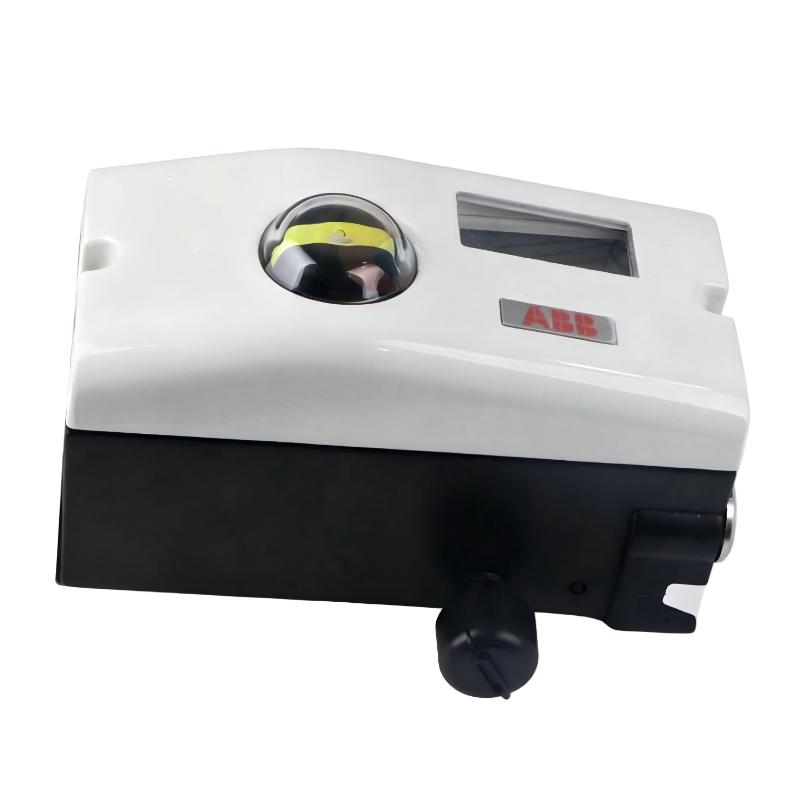
ABB V18345-2010521001 Mechanical Fault Diagnosis
When the valve reaches approximately the same physical position every time and then stops, inspect the mechanical system before replacing the positioner.
Check for:
Feedback arm reaching its mechanical limit
Incorrect mounting geometry
Loose linkage
Actuator stroke mismatch
Valve stem obstruction
Excessive packing friction
Incorrect coupling
This is particularly important because the TZIDC positioner is designed to work with both linear and rotary actuator arrangements.
A feedback mechanism that reaches its limit before the valve reaches its full stroke can create an apparently repeatable electronic fault.
The engineering test is simple: observe whether the mechanical feedback movement reaches the expected range at the same time as the valve.
ABB V18345-2010521001 Analog Feedback Fault Troubleshooting
The V18345-2010521001 configuration includes an analog position-feedback option with a 4–20 mA two-wire signal.
If the control position is correct but the remote feedback value is wrong, separate the problem into two possibilities:
Positioner control is correct but feedback scaling is incorrect.
or
The physical valve position is incorrect and the feedback is accurately reporting that condition.
For example, a DCS may display 65% while the local mechanical indicator appears close to 50%.
Do not immediately change the DCS scaling.
First establish the actual mechanical position. Then compare it with the positioner's internal position measurement and finally with the transmitted feedback current.
This three-point comparison is much more reliable than checking only the DCS screen.
ABB V18345-2010521001 Communication and Configuration Faults
Some TZIDC variants use digital communication and local configuration functions, while the exact capabilities depend on the ordering configuration. ABB documentation identifies the TZIDC family as supporting 4–20 mA two-wire operation and optional communication configurations.
If local configuration appears normal but the control system does not receive the expected information, verify the installed hardware configuration before attempting software changes.
A useful diagnostic order is:
Physical wiring → Loop current → Device configuration → Communication interface → DCS scaling
This avoids changing several parameters simultaneously and losing the original fault condition.
ABB V18345-2010521001 Pneumatic Instability Troubleshooting
A different failure pattern is valve hunting.
The valve may repeatedly move around its commanded position:
48% → 53% → 47% → 54% → 49%
When this occurs, check the process and mechanical system before assuming that the positioner tuning is wrong.
Potential causes include:
Unstable instrument air
Mechanical backlash
Valve friction
Incorrect feedback linkage
Process pressure fluctuations
Poorly selected control parameters
Excessive sensitivity in the control loop
The diagnostic goal is to determine whether the oscillation originates from the process command or from the positioner's response.
A trend showing both the command signal and actual valve position is particularly useful. If the command itself oscillates, the positioner may simply be following the controller.
ABB V18345-2010521001 Repair Decision Process
Replacing the complete positioner should be the final step, not the first.
Use this decision path:
Is the 4–20 mA signal correct?
If no, investigate the PLC/DCS analog output and field wiring.
Is the pneumatic supply stable?
If no, investigate the air system.
Does the positioner respond to the command?
If no, investigate configuration, electrical connections, and device condition.
Does the actuator move correctly when pneumatic output changes?
If no, investigate the actuator and valve.
Does the feedback mechanism accurately follow valve travel?
If no, correct the mechanical installation.
This Fault Diagnosis sequence isolates the failure rather than replacing components based only on symptoms.
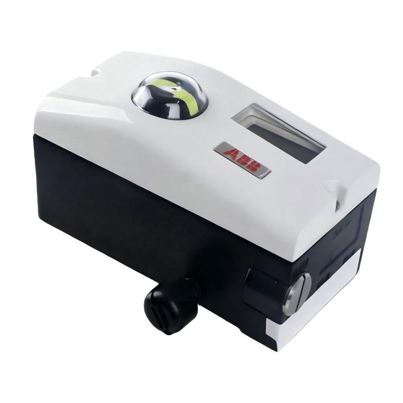
ABB V18345-2010521001 Field Fault Investigation
A useful field investigation begins with a valve that remains near its previous position even though the DCS command has changed.
Assume the operator reports that the valve is "stuck at 42%."
The first measurement should be the actual loop current.
If the DCS is commanding 14 mA and approximately 14 mA is measured at the positioner, the control signal has reached the field device.
Next, observe pneumatic behavior.
If the output pressure changes but the actuator does not move, the actuator or valve becomes the primary suspect.
If the output pressure does not change, continue upstream into positioner configuration and electrical response.
Only after these measurements should the positioner's electronics be considered a probable failure point.
This fault-isolation approach is especially useful during shutdown maintenance because it prevents unnecessary removal of a functioning positioner.
ABB V18345-2010521001 Troubleshooting Checklist
Before declaring the positioner defective, verify:
4–20 mA input is within the expected operating range.
Loop polarity is correct.
Pneumatic supply is clean and stable.
Actuator connections are correct.
Valve movement is mechanically free.
Feedback linkage is secure.
Positioner mounting is rigid.
Configuration matches the actuator.
Local position and actual valve travel agree.
Analog feedback, where fitted, has been checked independently.
DCS scaling corresponds to the installed signal range.
For hazardous-area installations, the applicable certification and wiring requirements must also be followed. ABB documentation specifies particular electrical parameters and installation restrictions for intrinsically safe versions of the TZIDC family.
ABB V18345-2010521001 Long-Tail Troubleshooting Keywords
Relevant long-tail search terms include:
ABB V18345-2010521001 troubleshooting
ABB V18345-2010521001 fault diagnosis
ABB V18345-2010521001 valve positioner repair
ABB V18345-2010521001 4–20 mA fault
ABB V18345-2010521001 valve not moving
ABB TZIDC positioner troubleshooting
ABB TZIDC pneumatic output problem
ABB V18345 position feedback fault
ABB V18345 valve positioner calibration problem
ABB V18345-2010521001 System Configuration fault
ABB V18345-2010521001 Practical Fault-Diagnosis Conclusion
The most useful Troubleshooting principle for the V18345-2010521001 is to follow the signal chain instead of guessing from the alarm message.
Start with:
Command → Current → Positioner → Pneumatic Output → Actuator → Valve → Feedback
A failed valve positioner is only one possibility within that chain.
For maintenance engineers, recording the actual current, pneumatic pressure, commanded position, measured position, and feedback signal provides much stronger evidence than simply recording "positioner fault" in the maintenance log.
The TZIDC documentation itself emphasizes the relationship between the positioner, actuator mounting, electrical input, pneumatic output, and optional feedback functions, making this system-level approach appropriate for Fault Diagnosis and commissioning work.

