ABB V18348-10113300110 TZIDC-200 Digital Positioner Installation Guide (Setup & Commissioning)
Time:2026-09-30 Browse: 0
ABB V18348-10113300110 TZIDC-200 installation depends heavily on correct mechanical feedback alignment, stable instrument air, and a properly configured 4–20 mA HART loop. The TZIDC-200 is a flameproof digital positioner designed for linear or rotary actuators, with automatic adjustment functions intended to simplify valve commissioning.
ABB V18348-10113300110 TZIDC-200 Positioner Role in a Valve Control System
The ABB V18348-10113300110 belongs to the TZIDC-200 digital positioner family. In a typical control loop, the PLC or DCS sends a 4–20 mA command, while the positioner compares the requested valve position with the measured actuator position and adjusts pneumatic output accordingly.
The device also supports HART communication, allowing configuration, diagnostics, maintenance information, and fault detection to be accessed without treating the positioner as a simple analog instrument.
For field engineers, this means the installation is not complete when the enclosure is physically mounted. The feedback mechanism, pneumatic circuit, current loop, and actuator travel must all agree before the valve can be considered commissioned.
ABB TZIDC-200 Installation Preparation and System Configuration
Before mounting the positioner, verify the exact V18348 ordering configuration against the nameplate and project documentation. The V18348 family uses configuration codes for housing, operation, safe position, feedback options, parameterization, and other design features, so the complete ordering number should not be treated as interchangeable with another TZIDC-200 variant.
For a normal commissioning job, prepare:
ABB V18348-10113300110 TZIDC-200 positioner
Correct actuator mounting bracket and feedback linkage
4–20 mA control wiring
Instrument air tubing and fittings
Calibrated pressure gauge where required
HART communicator or suitable configuration software
Approved tools for the applicable hazardous area
The instrument air supplied to the TZIDC-200 should be free from oil, water, and dust. ABB commissioning documentation specifies an instrument-air supply range of approximately 1.4 to 6 bar (20 to 90 psi).
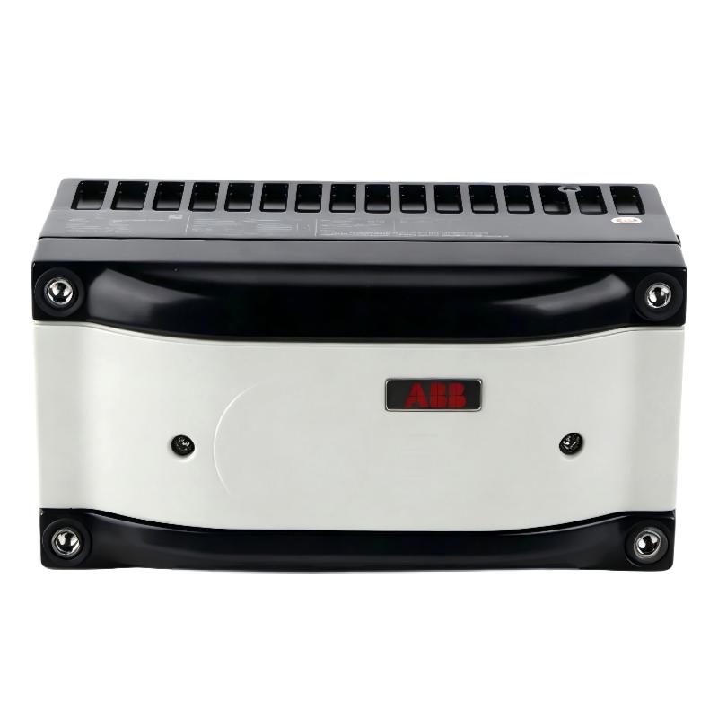
ABB V18348-10113300110 Mechanical Installation and Feedback Alignment
Mechanical alignment is one of the areas where installation problems are frequently introduced.
For a linear actuator, mount the bracket so that the positioner feedback lever operates symmetrically through its permitted range. The actuator stroke should correspond to an appropriate movement of the positioner feedback mechanism rather than forcing the lever against a mechanical limit.
ABB documentation recommends checking the operating range after mounting. The lever must remain within the specified feedback range during the complete valve stroke.
For a rotary actuator, the adapter position must be selected according to the actuator's initial position and direction of rotation. The adapter is secured to the feedback shaft, and the final installation must be checked to ensure that actuator movement corresponds correctly to the positioner's measuring range.
A practical field check is simple: move the valve manually through its available travel and observe the feedback mechanism. If the linkage approaches its mechanical stop before the valve reaches full travel, correct the mechanical setup before attempting automatic commissioning.
ABB TZIDC-200 Electrical Wiring and HART Setup
The standard TZIDC-200 analog input is connected at terminals +11 / −12. Optional feedback and binary functions use separate terminals depending on the installed configuration. For example, optional analog position feedback uses +31 / −32, while optional digital feedback uses dedicated terminals.
Do not assume that every terminal is present or active on every V18348 configuration. Check the actual device option code and wiring diagram before connecting external circuits.
For HART commissioning, verify the loop resistance and ensure that the current signal reaches the positioner without excessive voltage drop. A healthy 4–20 mA command should be evaluated together with the valve's actual mechanical position rather than checked in isolation.
In hazardous areas, installation must follow the applicable protection concept and local regulations. ABB specifically identifies restrictions concerning the integrated communication interface when the TZIDC-200 is installed in an explosion-risk area.
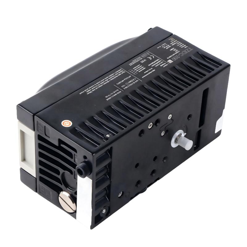
ABB V18348-10113300110 Pneumatic Connection Check
The pneumatic circuit determines how effectively the positioner can move the actuator.
The TZIDC-200 uses instrument air connections for actuator output, with OUT1 and, where applicable, OUT2 serving the actuator circuit. For a double-acting actuator, both pneumatic paths must be connected correctly according to the actuator design.
Before commissioning, check:
Air supply pressure
Tubing condition
Fitting tightness
Correct OUT1 / OUT2 connection
Actuator response to increasing and decreasing output pressure
Unexpected air leakage
If the valve moves slowly despite a correct electrical signal, investigate the pneumatic circuit before changing positioner parameters.
ABB TZIDC-200 Setup and Automatic Commissioning
Once mechanical, electrical, and pneumatic installation has been verified, perform the ABB TZIDC-200 setup procedure using the approved commissioning method for the specific configuration.
The positioner provides an automatic adjustment or Autostroke function that determines control parameters and adapts the device to the final control element. This is one reason the TZIDC-200 can reduce commissioning time compared with manually tuning every control parameter.
During Setup / Commissioning, observe the complete valve movement instead of simply waiting for the procedure to finish.
A useful engineering sequence is:
Command → feedback → pneumatic response → final valve position
If any one of these four elements behaves abnormally, stop the commissioning procedure and investigate that section rather than repeatedly restarting Autostroke.
ABB V18348-10113300110 Commissioning Validation
After automatic adjustment, test several operating points rather than checking only 0% and 100%.
For example:
| Command | Expected Observation |
|---|---|
| 4 mA | Valve approaches configured minimum position |
| 8 mA | Stable intermediate position |
| 12 mA | Approximately mid-range response |
| 16 mA | Stable upper-mid position |
| 20 mA | Valve approaches configured maximum position |
The exact relationship depends on actuator configuration, valve action, safe-position setup, and calibration.
During validation, compare the commanded position with the position reported by the positioner. A persistent offset should trigger a review of mechanical alignment and configuration before the control loop is released to automatic operation.
ABB TZIDC-200 Field Commissioning Experience
In one valve commissioning case, the electrical loop measured correctly at approximately 12 mA, but the valve did not settle near its expected mid-travel position. The initial suspicion was an incorrect positioner configuration.
The commissioning engineer instead checked the feedback linkage first. The lever was mechanically biased toward one end of its usable range, leaving insufficient symmetrical travel. After correcting the bracket position and repeating the automatic adjustment, the valve response became stable across the operating range.
This illustrates an important ABB TZIDC-200 Installation Guide principle: do not use software calibration to compensate for poor mechanical installation.
ABB V18348-10113300110 Installation and Commissioning Long-Tail Keywords
Common search terms associated with this application include:
ABB V18348-10113300110 installation guide
ABB TZIDC-200 digital positioner installation
ABB TZIDC-200 setup and commissioning
ABB V18348 positioner wiring
TZIDC-200 HART commissioning
ABB TZIDC-200 actuator calibration
TZIDC-200 Autostroke setup
ABB digital positioner system configuration
TZIDC-200 valve positioner commissioning
A reliable installation is achieved when the mechanical feedback, pneumatic supply, 4–20 mA input, HART configuration, and actuator travel have been verified as one integrated system.

