ABB V18348-10113300110 TZIDC-200 Positioner Fault Diagnosis & Troubleshooting Guide
Time:2026-09-30 Browse: 0
ABB V18348-10113300110 TZIDC-200 troubleshooting should begin with the relationship between command current, position feedback, pneumatic output, and actual valve movement. When a TZIDC-200 valve positioner reports an incorrect position or the actuator stops responding, replacing the electronics immediately can hide the real cause.
ABB V18348-10113300110 TZIDC-200 Fault Symptoms
A common field symptom is a valve that reaches the commanded position but repeatedly oscillates around the setpoint. Another pattern is a stable 4–20 mA command accompanied by slow or incomplete valve movement.
Typical symptoms include:
Valve position does not follow the PLC command
Position feedback remains almost constant
Valve moves in the wrong direction
Excessive hunting around the setpoint
Autostroke does not complete normally
HART communication is intermittent
Valve reaches one end of travel but not the other
Position deviation remains after commissioning
The first distinction is whether the problem is electrical, mechanical, pneumatic, or configuration-related.
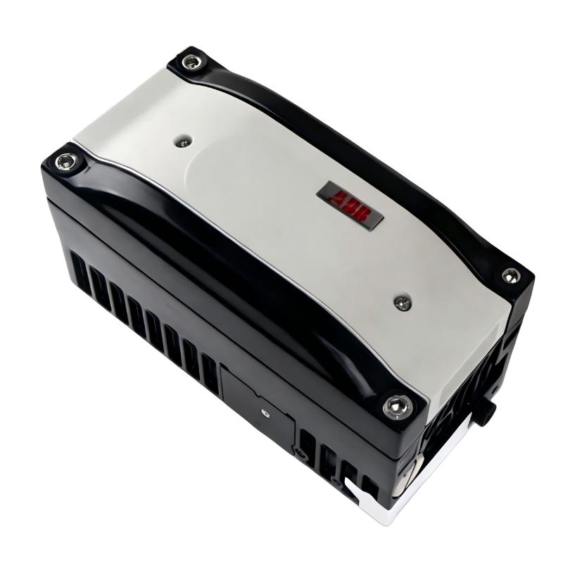
ABB TZIDC-200 Fault Diagnosis: Start With the 4–20 mA Signal
Suppose the PLC output is commanding 50%, but the valve remains near its previous position.
Do not immediately conclude that the TZIDC-200 has failed.
Measure the actual loop current at the positioner.
A simplified diagnostic logic is:
PLC output → measured loop current → TZIDC-200 input → position feedback → pneumatic output → valve position
If the PLC indicates 12 mA but only 7 mA reaches the positioner, the positioner itself may be functioning normally. The investigation should move toward the loop wiring, barriers, terminals, or other components between the control system and field device.
Conversely, if the positioner receives a stable 12 mA and its reported position changes incorrectly, the investigation should move downstream toward feedback and actuator behavior.
ABB V18348-10113300110 Position Feedback Fault Analysis
A positioner can receive the correct command while reporting an incorrect valve position if its mechanical feedback system is incorrectly installed.
Check the feedback lever and linkage for:
Loose fixing hardware
Incorrect mounting angle
Excessive mechanical play
Linkage interference
Insufficient operating travel
Feedback mechanism approaching its mechanical limit
ABB documentation specifically requires the actuator operating range to be checked against the positioner's measuring range after mounting.
This is particularly important after valve maintenance. A technician may reinstall the actuator or bracket slightly differently, creating a feedback error that appears to be an electronic calibration problem.
ABB TZIDC-200 Troubleshooting for Slow Valve Movement
Slow response does not automatically indicate a defective positioner.
The pneumatic side should be checked first.
Measure the instrument-air pressure at the positioner rather than relying only on the pressure shown elsewhere in the plant. ABB commissioning documentation specifies an air supply range of 1.4–6 bar (20–90 psi), while the actual operating requirement must also match the actuator and process design.
Then inspect the tubing and actuator.
A useful comparison is:
Correct current + weak pneumatic response = investigate air path
Correct current + normal pneumatic output + poor valve movement = investigate actuator or valve mechanics
This separation prevents unnecessary replacement of the digital positioner.
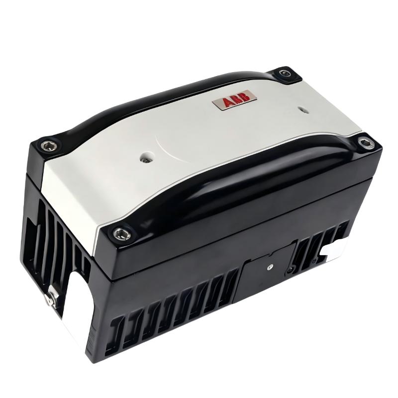
ABB V18348-10113300110 HART Communication Troubleshooting
HART communication problems require a different diagnostic approach from a basic analog-loop fault.
The TZIDC-200 uses 4–20 mA HART communication for configuration and diagnostic access.
If the analog control signal remains stable but HART communication drops intermittently, inspect:
Loop resistance and wiring quality.
Cable shielding and grounding arrangement.
Terminal tightness.
HART communicator connection point.
Installed device configuration.
Electrical interference from nearby equipment.
If the process valve continues to follow the 4–20 mA command while HART access is lost, this distinction is important: the communication layer may be faulty while the basic analog control loop remains operational.
That is a different failure mode from a complete positioner power or input failure.
ABB TZIDC-200 Fault Diagnosis for Valve Hunting
Valve hunting is often blamed on the positioner immediately, but the actual cause can involve the entire control loop.
First observe whether the commanded position from the PLC/DCS is itself moving.
For example:
12.0 mA → 12.5 mA → 11.8 mA → 12.4 mA
If the command is continuously changing, the positioner may simply be following an unstable control signal.
If the command remains close to 12.0 mA while the valve position repeatedly moves around the target, investigate the positioner setup, feedback linkage, pneumatic dynamics, and actuator behavior.
The diagnostic principle is simple: prove that the input is stable before judging the output response.
ABB V18348-10113300110 Real Field Fault: Position Deviation After Valve Maintenance
A representative field failure pattern occurred after a control valve actuator had been removed for maintenance.
The PLC output was normal, and the TZIDC-200 received approximately 16 mA during the test. However, the reported valve position remained several percentage points away from the expected value.
The first assumption was an incorrect analog calibration.
The engineer instead compared the physical valve travel with the positioner's feedback movement. The linkage had been reassembled with a different mechanical starting position. As a result, the feedback mechanism no longer used its travel range symmetrically.
After correcting the mechanical alignment and repeating the positioner adjustment, the position deviation disappeared.
The lesson for TZIDC-200 Fault Diagnosis is important: a position error appearing immediately after mechanical maintenance should be investigated mechanically before replacing the electronics.
ABB TZIDC-200 Troubleshooting for Autostroke Failure
When automatic commissioning does not complete, examine the physical movement during the procedure.
Ask three questions:
Does the actuator move?
If not, check instrument air, pneumatic connections, actuator condition, and output response.
Does the feedback value change when the actuator moves?
If the actuator moves but the feedback does not respond correctly, investigate the mechanical feedback arrangement.
Does the feedback change in the wrong direction?
If so, inspect actuator direction, mounting orientation, and configuration.
ABB's TZIDC-200 is designed with an automatic adjustment function, but automatic commissioning cannot correct a fundamentally incorrect mechanical installation.
ABB TZIDC-200 Troubleshooting and System Configuration Checks
If mechanical and pneumatic checks are satisfactory, review the stored configuration.
Pay particular attention to:
Valve travel direction
Actuator type
Fail-safe behavior
Input scaling
Position feedback
Automatic adjustment status
HART communication parameters
Optional feedback modules
The TZIDC-200 family supports different actuator arrangements and configuration options, so the exact parameter set should be checked against the installed V18348 variant rather than copied blindly from another positioner.
ABB V18348-10113300110 Fault Diagnosis Long-Tail Keywords
Useful long-tail search phrases for field troubleshooting include:
ABB V18348-10113300110 troubleshooting
ABB TZIDC-200 troubleshooting guide
ABB TZIDC-200 fault diagnosis
TZIDC-200 valve positioner fault
ABB TZIDC-200 position feedback problem
TZIDC-200 Autostroke failure
ABB TZIDC-200 HART communication fault
ABB V18348 digital positioner repair
TZIDC-200 valve position deviation
ABB digital positioner pneumatic troubleshooting
The most effective Troubleshooting method is to isolate the signal path rather than replacing components based only on the alarm or symptom. For the ABB V18348-10113300110, the decisive evidence normally comes from comparing the 4–20 mA command, position feedback, pneumatic response, and actual valve travel.

