Foxboro RH916FK Termination Cable Troubleshooting for Intermittent DCS Signals
Time:2026-10-09 Browse: 0
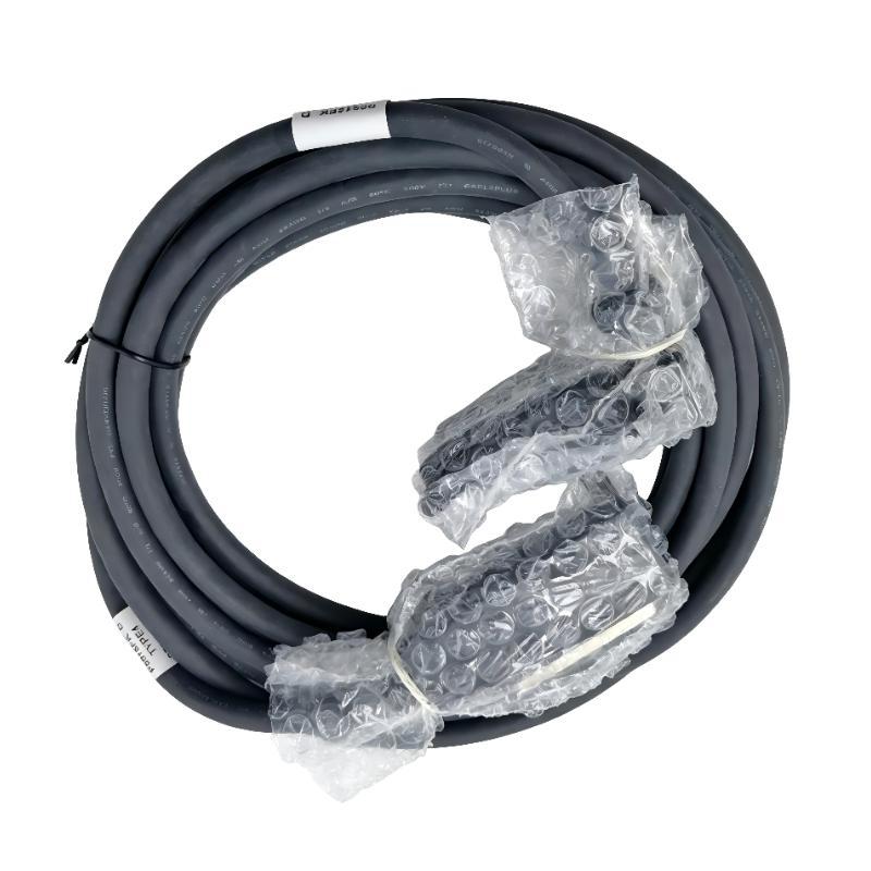
Intermittent signals associated with a Foxboro RH916FK termination cable should be investigated by separating cable-connection problems from termination assembly faults, channel configuration errors, and field-device issues. The RH916FK is a 5-meter Type 4 P/PVC termination cable, but the presence of an abnormal DCS indication does not by itself prove that the cable has failed.
Diagnosing Intermittent Signals on the Foxboro RH916FK
An intermittent signal can appear normal during initial commissioning and then become unstable after cabinet maintenance, vibration, or repeated access to the equipment. Engineers should record the affected channel, alarm history, module diagnostic status, and timing of the abnormal indication before disturbing the wiring.
Three observations help narrow the investigation:
One channel affected: Investigate the field circuit, channel-specific termination, and associated configuration first.
Several channels affected simultaneously: Examine shared hardware, common termination connections, and module-level diagnostics.
Faults occur after cabinet access: Inspect connector seating, cable strain, and any wiring disturbed during maintenance.
These patterns are diagnostic clues, not conclusive proof of a particular failure.
A Practical RH916FK Fault Diagnosis Sequence
Begin by confirming whether the fault is repeatable and whether it coincides with a process event, cabinet activity, or a system alarm.
Next, compare the observed signal with the expected field condition. For an analog input, compare the reported value with an independently verified field measurement where the circuit design permits. For a discrete input, compare the channel state with the actual contact or voltage condition specified by the system documentation.
If the field condition is correct but the DCS indication is inconsistent, inspect the termination assembly and cable connection under the approved isolation procedure. Check for incomplete seating, damaged contacts, contamination, or mechanical stress.
Only after these checks should the engineer consider a controlled cable substitution using a verified compatible cable. Follow the site's change-control procedure and preserve the original wiring arrangement so that the test does not introduce a second fault.
Case Analysis: DCS Channel Drops Out After Cabinet Maintenance
Reported symptom: A channel becomes intermittently unavailable after maintenance in a control cabinet.
Initial observation: The module shows no confirmed hardware failure, but the channel indication changes unexpectedly. This observation narrows the investigation without eliminating a connection fault.
Engineering reasoning: Because the symptom appeared after cabinet work, the engineer prioritizes disturbed connectors, cable routing, and termination interfaces. The RH916FK identification and the corresponding hardware compatibility are checked against the approved drawings.
Corrective action: If a connection is found to be incompletely seated, the affected equipment is placed in the required safe maintenance state, and the connection is corrected in accordance with the manufacturer's instructions. The engineer then verifies channel stability and checks for recurring diagnostic events.
This is an illustrative field case. No actual customer incident, confirmed root cause, or measured recovery result is claimed.
Distinguishing Cable Damage from Configuration Faults
Not every signal problem requires cable replacement. A wrong channel assignment, incompatible termination assembly, incorrect module configuration, or defective field device can produce symptoms similar to a wiring fault.
Use the following diagnostic logic:
If multiple channels report related faults, examine common hardware and shared connections.
If one channel is affected and the field device is operating normally, inspect its specific signal path.
If the fault began after a configuration change, review the module setup and channel mapping.
If connector inspection reveals physical damage, arrange a controlled replacement with the correct cable type.
If the fault persists after a verified cable substitution, return to the termination assembly, module diagnostics, and field circuit rather than repeatedly changing cables.
Never use an improvised continuity or resistance test on an energized control circuit. Any electrical measurement must be appropriate to the circuit design and performed under the site's safety procedures.
Foxboro RH916FK Repair and Recovery Verification
After correcting the suspected cause, verify the repair against the original symptom. Confirm that the affected channel follows the expected field condition, module diagnostics remain acceptable, and no new alarms appear during the approved observation period.
Record the cable part number, termination assembly identification, observed fault, corrective action, and commissioning result. If the fault returns, preserve the diagnostic history and investigate whether the failure is temperature-related, vibration-related, or associated with a particular operating event.
The goal of Troubleshooting is to establish a defensible root cause, not merely to clear an alarm.
Long-Tail Keywords for RH916FK Troubleshooting
Relevant technical search topics include Foxboro RH916FK termination cable troubleshooting, RH916FK intermittent DCS signal fault diagnosis, Foxboro Type 4 cable connection problems, and RH916FK cable replacement during DCS commissioning.
For each case, the most reliable approach is to confirm compatibility, examine the physical connection, correlate the channel indication with the field condition, and validate the repair under normal approved operating conditions.

