Foxboro RH916FK Termination Cable Installation Guide for DCS Setup and Commissioning
Time:2026-10-09 Browse: 0
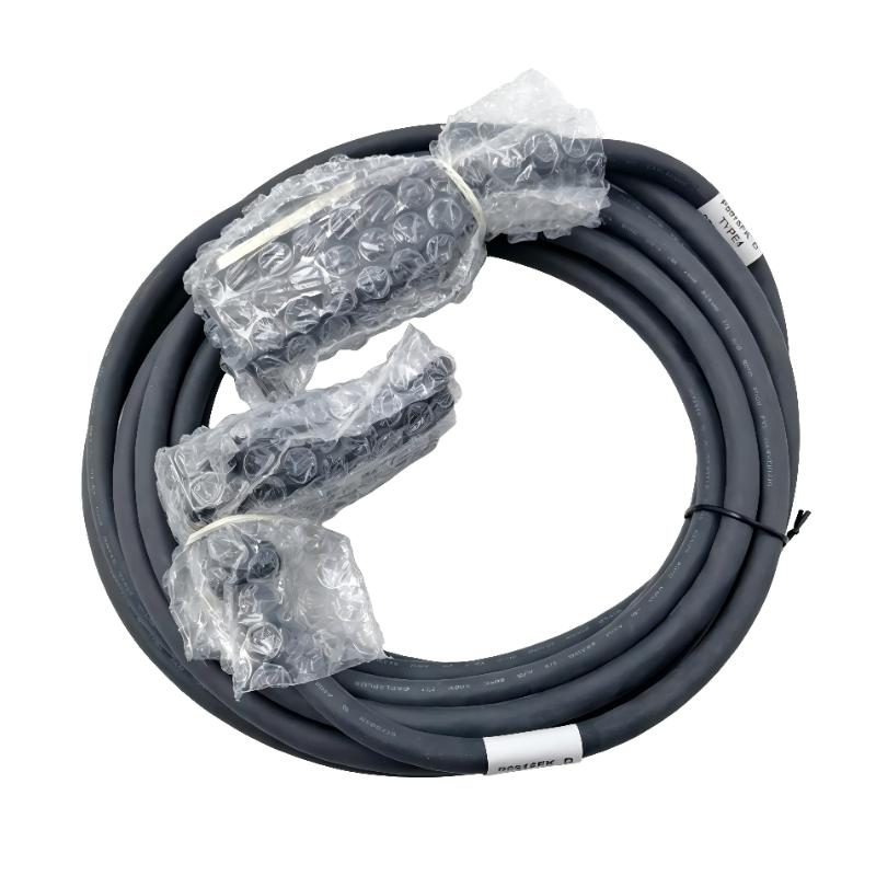
The Foxboro RH916FK termination cable is a 5-meter Type 4 P/PVC cable used to connect compatible Foxboro distributed control system (DCS) components and termination assemblies. Correct installation depends on matching the cable to the required fieldbus module (FBM), termination assembly, connector arrangement, and system configuration rather than cable length alone.
Foxboro RH916FK Cable Function in DCS Installation
The RH916FK provides an electrical connection between compatible Foxboro control hardware and its termination assembly. In a DCS installation, this connection supports the intended signal path between the control module and the associated termination hardware.
Before using this cable, engineers should confirm that the relevant Foxboro hardware documentation specifies RH916FK or an approved equivalent. The model designation identifies a particular cable configuration, so physical connector similarity does not guarantee electrical compatibility.
Installation Preparation and System Configuration
A practical Installation Guide begins with hardware verification. Confirm the following information before connecting the cable:
Cable model: Foxboro RH916FK.
Cable length: 5 meters.
Cable type: Type 4 P/PVC, as identified in applicable Foxboro documentation.
Compatible hardware: Verify the FBM and termination assembly part numbers against the system documentation.
Routing requirements: Check cable tray capacity, bend radius, connector access, and separation from electrical noise sources.
The P/PVC construction uses a polyurethane outer jacket and semirigid PVC primary conductor insulation. Applicable product documentation should be consulted for the exact temperature rating and environmental limitations.
RH916FK Wiring and Physical Connection Checks
Before connecting the RH916FK, place the affected equipment in the approved maintenance state and follow the site's isolation procedures. Never disconnect control-system cabling on an operating process without evaluating the consequences.
Inspect the connectors for bent contacts, contamination, damaged locking features, or signs of moisture. Route the cable without tension and avoid tight bends, sharp metal edges, and unnecessary proximity to high-current switching conductors.
Connect both ends according to the designated hardware interfaces. Do not force a connector into position or assume that a matching shell confirms pin compatibility. Secure the cable so that routine cabinet access does not pull on the connector.
RH916FK Setup and Commissioning Validation
After installation, inspect the cable route and verify that each connection is fully seated. Restore the equipment according to the approved commissioning procedure.
During Setup / Commissioning, check:
Whether the intended module and termination assembly are recognized and healthy.
Whether relevant channel diagnostics show unexpected faults.
Whether field signals agree with the expected operating conditions.
Whether the cable identification matches the approved drawings and maintenance records.
For example, if a commissioned channel reports an abnormal state, compare the channel indication with the field-device state and inspect the termination path before replacing the module. A healthy module status alone does not establish that every individual connection is correct.
Field Example: RH916FK Commissioning Inspection
Consider a commissioning scenario in which an input channel remains inactive after a replacement cable is installed. The engineer first verifies the RH916FK part number and its 5-meter length, then checks both connector interfaces and compares the installation with the approved wiring diagram.
If the channel remains inactive, the next checks should include termination compatibility, channel assignment, and the relevant module diagnostics. This is an illustrative diagnostic scenario, not a claim of a documented customer repair or measured test result.
The important engineering principle is to verify the entire connection path before concluding that the cable itself is defective.
Foxboro RH916FK Installation Guide: Long-Tail Technical Checks
Common installation questions include how to install a Foxboro RH916FK termination cable, how to verify RH916FK DCS cable compatibility, and how to commission a Foxboro Type 4 P/PVC cable in a control cabinet.
The answer depends on the actual FBM and termination assembly combination. Use the applicable Foxboro hardware documentation to confirm compatibility, connector orientation, and commissioning requirements.
A correctly identified cable, mechanically sound connections, and documented System Configuration checks provide a more reliable basis for commissioning than replacing components through trial and error.

