Schneider ATS22D47Q Soft Starter Installation Guide (Wiring & Commissioning)
Time:2026-10-10 Browse: 0
Schneider ATS22D47Q Soft Starter Installation Overview
The Schneider ATS22D47Q soft starter requires correct motor current configuration, secure three-phase power connections, and a verified control circuit to achieve reliable motor starting. As an Altistart 22 series soft starter, it is designed for three-phase asynchronous motors, with a rated current of 47 A and a rated supply voltage range of 230–440 V. Its motor power rating reaches 22 kW at 400–440 V, making it suitable for applications such as pumps, fans, and other industrial motor-driven equipment.
A successful Installation Guide should focus on more than mounting the device. The Setup / Commissioning process must also confirm the motor nameplate data, starting requirements, control voltage, and protection settings before the equipment enters normal operation.
Schneider ATS22D47Q Electrical Requirements and Preparation
Before installation, verify that the ATS22D47Q nameplate matches the supply system and motor application. This model uses a 230 V AC control supply and 24 V DC logic inputs. Confusing the control supply with the logic input voltage can result in incorrect wiring or equipment damage.
The principal specifications are:
Product type: Altistart 22 soft starter
Rated current: 47 A
Rated supply voltage: 230–440 V AC
Motor power: 11 kW at 230 V; up to 22 kW at 400–440 V
Control circuit voltage: 230 V AC
Logic input voltage: 24 V DC
Communication: Modbus via RJ45 interface
Protection rating: IP20
Inspect the enclosure, terminals, cooling passages, and wiring accessories before mounting. Any equipment showing transport damage should be investigated before energization.
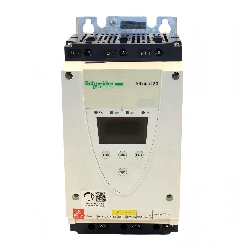
ATS22D47Q Mounting, Power Wiring, and Control Connections
Install the Schneider ATS22D47Q vertically, following the manufacturer’s clearance and ventilation requirements. Avoid placing it directly beside heat-producing equipment or stacking soft starters in a way that restricts airflow. In a crowded motor control cabinet, inadequate heat dissipation can cause thermal trips even when the motor current is within its expected operating range.
For the main circuit, connect the incoming three-phase supply and motor terminals according to the official ATS22 wiring diagram. Confirm the protective earth connection, conductor sizing, terminal preparation, and tightening torque. The published terminal tightening torque for the relevant power connections is 3 N·m; verify the applicable terminal specifications in the current manual before work begins.
The control circuit should be checked independently of the power circuit. Confirm the 230 V AC control supply and wire the LI1, LI2, and LI3 logic inputs according to the selected two-wire or three-wire control arrangement. Do not assume that a PLC output can directly provide the required signal without checking its electrical characteristics and the starter's input requirements.
Schneider ATS22D47Q System Configuration and Commissioning
The most important commissioning task is matching the soft starter configuration to the actual motor and mechanical load. Enter the motor rated current from the motor nameplate and verify the selected current limit, acceleration ramp, and stopping behavior against the application requirements.
For a centrifugal pump, the commissioning objective may be to limit starting current while reducing hydraulic shock. For a fan with high inertia, a longer acceleration ramp may be necessary. These adjustments must remain within the motor's thermal limits and the starter's permitted operating conditions.
During Setup / Commissioning, use the following engineering checks:
Confirm that the motor and supply voltage ratings are compatible.
Verify the motor rated current and the configured protection values.
Test the start and stop commands without bypassing safety interlocks.
Observe phase current and acceleration behavior during the first loaded start.
Confirm that the ready, running, and fault relay signals match the control system logic.
Verify Modbus communication settings if the starter is monitored by a PLC or supervisory system.
Schneider ATS22D47Q First-Start Validation and Field Checks
A useful commissioning record includes the supply voltage, motor nameplate current, measured starting current, acceleration time, fault history, and final parameter settings. Record these values during a controlled test rather than relying only on the front-panel indication.
For example, if a pump motor accelerates smoothly without excessive current or abnormal mechanical noise, the next check is whether the motor reaches stable operating speed and the control system receives the correct running feedback. If the starter trips during acceleration, do not immediately increase the current limit. First determine whether the cause is excessive mechanical load, an incorrect motor-current setting, supply voltage imbalance, or an unsuitable ramp configuration.
Field engineering note: A commissioning case should be documented using actual measured values. Without recorded site measurements, specific starting-current reductions or commissioning improvements should not be presented as verified results.
Schneider ATS22D47Q Installation Guide: Long-Tail Commissioning Checks
For engineers searching for a Schneider ATS22D47Q soft starter wiring diagram, motor current setting procedure, or PLC control configuration, the practical priority is to validate each interface separately. Main power wiring, 230 V AC control power, 24 V DC logic inputs, relay feedback, and Modbus communication should each be tested against the applicable wiring diagram.
The final System Configuration should be saved in the maintenance record, together with the motor data and protection settings. Before releasing the equipment for continuous operation, confirm that the emergency-stop circuit, upstream protection, motor overload protection, and restart behavior meet the machine's safety requirements.
Always use the official Schneider Electric Altistart 22 user manual for model-specific terminal identification, parameter definitions, and commissioning limits.

