GE 8220-DI-IS Discrete Input Module Fault Diagnosis for Open-Circuit Alarms
Time:2026-10-15 Browse: 1
GE 8220-DI-IS Open-Circuit Faults: Symptoms and Initial Diagnosis
A GE 8220-DI-IS 16-channel Discrete Input Module open-circuit alarm can indicate a broken field conductor, a loose terminal, an incorrectly connected proximity detector, or a fault in the field loop. Because this PAC8000 module supports intrinsically safe switches and proximity detectors, an unexpected input state should be investigated through both electrical diagnostics and the application configuration.
The module supports field wiring fault detection, including open-circuit detection above 90 kΩ and short-circuit detection below 100 Ω. These are documented diagnostic thresholds, not universal resistance limits for every sensor type or operating condition.
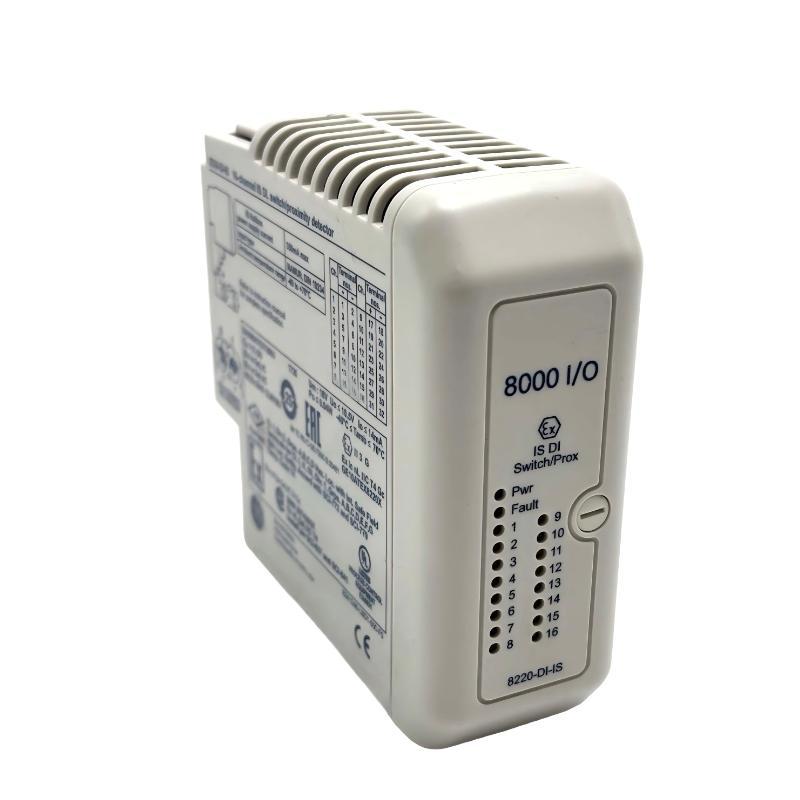
GE 8220-DI-IS Fault Symptoms in the PAC8000 Controller
An open-circuit fault may appear in several ways:
A discrete input remains inactive even when the field device should be operating.
The engineering display reports a line fault on a specific channel.
A proximity detector changes state locally, but the corresponding controller input does not respond.
A field input operates intermittently when a terminal or cable connection is disturbed.
The first task is to determine whether the problem is limited to one channel or affects several inputs. A single-channel fault suggests a localized loop problem, although a shared terminal or return connection can affect multiple channels. Several simultaneous faults warrant examination of common wiring, terminal arrangements, configuration changes, and module diagnostics.
Do not conclude that the input module has failed solely because the controller reports an abnormal input state.
GE 8220-DI-IS Troubleshooting: Follow the Fault from Sensor to Controller
The diagnostic sequence should follow the physical signal path.
Field device: Verify that the dry contact or proximity detector is suitable for the intrinsically safe input circuit and that it operates mechanically or electronically as intended.
Field wiring: Compare the actual conductor connections with the approved loop drawing. Inspect terminal tightness, cable damage, connector condition, and any maintenance changes that may have disturbed the loop.
Field terminal: Check that the installed terminal type is approved for the 8220-DI-IS and that the relevant channel connections correspond to the project drawings.
Module diagnostics: Review the channel status, module health, and relevant event records using the supported PAC8000 diagnostic tools.
Application mapping: If the physical channel appears healthy but the displayed PLC tag remains incorrect, verify the channel assignment and application logic.
This method separates a physical wiring fault from a configuration problem and avoids unnecessary replacement of a working module.
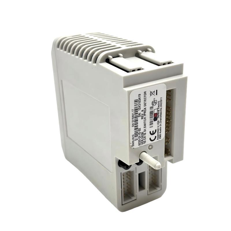
Case Analysis: Why a GE 8220-DI-IS Input Remains Inactive
In a representative maintenance scenario, a field proximity detector operates, but the corresponding PAC8000 input remains inactive and the channel reports an open-circuit condition.
The initial temptation may be to replace the detector. A more reliable approach is to verify the loop in sequence.
First, confirm the sensor's actual switching behavior. Next, inspect the field wiring and terminal identification against the approved drawing. Then review the channel diagnostic and verify that the configured input corresponds to the physical terminal being tested.
If the field loop is intact but the reported fault persists, examine the approved loop design, device compatibility, and terminal assembly before suspecting the module itself. Any electrical testing in a hazardous area must follow the site's permit, isolation, and intrinsic safety procedures.
This case illustrates a diagnostic method rather than a verified customer repair. No unmeasured resistance, voltage, or recovery result is presented as field evidence.
GE 8220-DI-IS Line Fault Detection and Electrical Limits
The 8220-DI-IS supports open- and short-circuit field wiring detection. Its published thresholds are:
| Diagnostic parameter | Documented value |
|---|---|
| Short-circuit detection | Below 100 Ω |
| Open-circuit detection | Above 90 kΩ |
| Input OFF current | Below 1.2 mA |
| Input ON current | Above 2.1 mA |
| Nominal switching hysteresis | 200 μA |
| Maximum input response time to Railbus | 6 ms |
These values provide useful reference points for Fault Diagnosis, but they must be interpreted within the specified sensor interface and installation conditions.
The input uses a low-energy intrinsically safe circuit. Do not apply an external 24 VDC source or an arbitrary insulation tester directly to the field terminals. Use only test methods permitted by the manufacturer's documentation and the approved hazardous-area procedure.
If the line fault appears only intermittently, review the diagnostic event timestamps and correlate them with equipment vibration, cable movement, moisture exposure, or recent maintenance. These are possible investigative leads, not proof of a particular root cause.
GE 8220-DI-IS Configuration Faults That Resemble Wiring Problems
Not every abnormal input is caused by an open conductor. Incorrect filtering, latching, pulse-counting settings, or channel mapping can make a correctly wired signal appear to be faulty.
For example, an input configured with a long filter may respond more slowly than the process engineer expects. A latched input may retain a state after the physical signal changes, depending on the configured latch behavior. A pulse-counting channel may behave differently from a conventional state-monitoring input.
Check the configuration against the intended application before modifying the hardware. If the diagnostic status is normal but the displayed state is incorrect, verify the physical channel-to-tag relationship and the application's interpretation of that channel.
Changes should be made through the supported engineering tools and the site's change-control procedure. Preserve the existing configuration before downloading a correction.
Restoring GE PAC8000 Input Operation After Fault Correction
After identifying and correcting the confirmed fault, validate the affected channel through the same conditions that originally produced the alarm. Confirm that the field device changes state, the channel diagnostic clears as expected, and the correct PLC tag follows the physical input.
For installations using line fault detection, verify both normal switching and the relevant fault indication under an approved test procedure. Check adjacent channels if the fault involved shared wiring or terminal hardware.
If the alarm returns, retain the diagnostic timestamps and configuration details. Repeated alarms after a wiring repair may indicate an unresolved connection issue, incompatible field-device characteristics, or a configuration mismatch. Replace the module only after external wiring, terminal compatibility, configuration, and available module diagnostics have been assessed.
GE 8220-DI-IS Troubleshooting Guide: Long-Tail Fault Diagnosis Checklist
For GE 8220-DI-IS 16-channel Discrete Input Module troubleshooting, prioritize the following long-tail diagnostic topics:
GE 8220-DI-IS open-circuit input fault diagnosis.
PAC8000 intrinsically safe digital input wiring troubleshooting.
8220-DI-IS proximity detector signal failure.
PAC8000 discrete input line fault detection.
GE 8220-DI-IS channel mapping and configuration errors.
A useful repair report should document the affected channel, the initial diagnostic indication, the field-device type, the verified wiring condition, the configuration revision, and the post-repair functional test. This evidence-based process helps prevent repeat failures and supports reliable maintenance of the PAC8000 control system.

