GE 8220-DI-IS 16-Channel Discrete Input Module Installation and Commissioning Guide
Time:2026-10-15 Browse: 1
GE 8220-DI-IS Installation Guide for Intrinsically Safe Digital Inputs
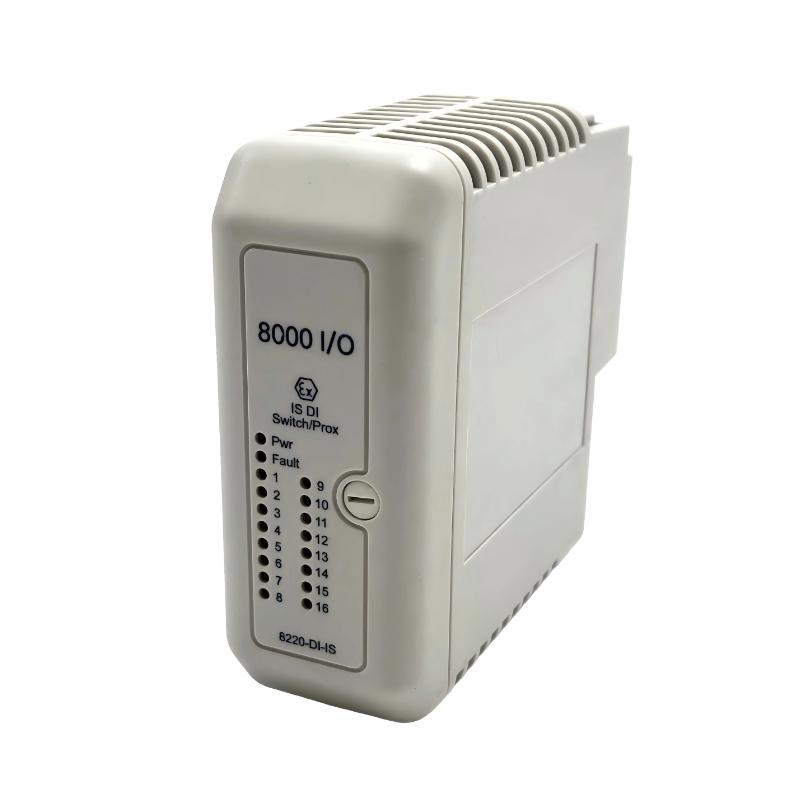
The GE 8220-DI-IS 16-channel Discrete Input Module requires correct intrinsically safe field wiring, compatible PAC8000 terminal hardware, and verified channel configuration before commissioning. Designed for switch and proximity detector signals, this module supports dry contacts and intrinsically safe proximity detectors in industrial process applications. Its documented functions include open-circuit and short-circuit field wiring detection, input latching, and pulse counting.
Unlike a conventional 24 VDC digital input module, the 8220-DI-IS must be installed according to the approved intrinsic safety design. Incorrect terminal selection, unsuitable sensor wiring, or incompatible hazardous-area parameters can compromise both signal acquisition and explosion protection.
GE 8220-DI-IS Module Preparation and Hardware Compatibility
Before installation, verify the complete model number, module key code, firmware compatibility, and PAC8000 system configuration. Confirm that the selected field terminal is approved for the 8220-DI-IS and that the installed carrier and Railbus arrangement match the system documentation.
The installation preparation should cover:
The 8220-DI-IS module and compatible intrinsically safe field terminal.
The approved hazardous-area wiring drawings and loop schedules.
The PAC8000 I/O configuration and engineering software.
The connected dry-contact switches or intrinsically safe proximity detectors.
Suitable test instruments and the site's hazardous-area work permit.
Check the module and terminal assembly for damaged connectors, contamination, loose mounting hardware, or signs of overheating. Confirm that the module is assigned to the correct controller and that its intended 16 input channels are represented correctly in the application configuration.
Intrinsically Safe Wiring Requirements for the GE 8220-DI-IS
The 8220-DI-IS provides intrinsically safe field circuits for approved switches and proximity detectors. The manufacturer's documentation specifies a maximum open-circuit output voltage of 10.5 V, a maximum short-circuit current of 14 mA, and a maximum output power of 0.04 W per channel. These parameters must be considered alongside the applicable certification and field-device entity parameters.
Do not treat these values as permission to connect arbitrary field devices. Verify the complete loop calculation, cable capacitance and inductance, sensor compatibility, grounding arrangements, and hazardous-area segregation requirements.
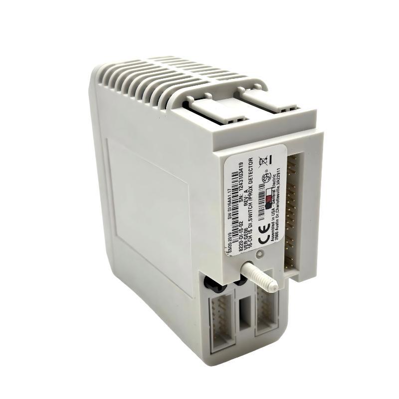
The module documentation also identifies 8623-FT-IS and 8624-FT-IS as compatible field-terminal options. Confirm the precise terminal arrangement against the applicable hardware revision before wiring.
Each field channel should be checked against the approved loop drawing. Pay attention to common returns, terminal identification, and the separation of intrinsically safe circuits from non-intrinsically safe wiring. Never assume that a terminal layout for another PAC8000 digital input module applies to the 8220-DI-IS.
GE PAC8000 System Configuration and Input Setup
Once the module is mounted and the field wiring has been inspected, establish the correct System Configuration in the supported PAC8000 engineering environment.
Review the channel assignments and confirm that each physical input corresponds to the intended application tag. Configure the input filter according to the expected switch behavior and signal characteristics. The 8220-DI-IS supports fast, slow, or user-defined filtering, with documented user-defined values from 0 to 512 ms in 3 ms increments.
The following options also require attention:
Input latching: Enable or disable latching according to the application requirements, and select the appropriate latch polarity.
Pulse counting: Enable this function only when the input is intended to capture pulse events. The documented maximum pulse-counting frequency is 20 Hz, with a minimum pulse width of 45 ms.
Line fault detection: Configure open- and short-circuit detection where required by the approved loop design. The documented thresholds are below 100 Ω for a short circuit and above 90 kΩ for an open circuit.
Filter selection, latching, pulse counting, and line fault detection should be validated against the process requirements rather than copied indiscriminately from another controller configuration.
GE 8220-DI-IS Setup and Commissioning Tests
During Setup / Commissioning, begin with module health and communication status. Confirm that the controller recognizes the module, the expected channel count is available, and no unexplained module or Railbus diagnostics remain active.
Next, test representative field inputs using the approved site procedure. For a dry-contact channel, verify that the open and closed states are reflected correctly in the engineering display. For a proximity detector, compare the actual sensor state with the corresponding controller input and confirm that the selected filter does not suppress valid transitions.
Where line fault detection is configured, perform the approved open- and short-circuit tests only under controlled conditions and with the required hazardous-area authorization. Confirm that the resulting diagnostics are distinguishable from normal switching events.
Record the observed state, diagnostic indication, configured filter, and relevant event timestamps. The documented maximum response time from a field event to data availability on the Railbus is 6 ms; this is a module specification, not a guarantee of total end-to-end SCADA response time.
Field Commissioning Example: GE 8220-DI-IS Proximity Detector Validation
Consider a representative commissioning situation in which a proximity detector is physically switching, but its assigned PLC tag remains unchanged. Replacing the detector immediately would be premature.
The engineer first verifies the sensor's physical operation and checks the field-terminal wiring against the approved loop drawing. The next step is to inspect the input channel's diagnostic status and verify the System Configuration, including channel mapping and input filtering.
If the channel reports an open-circuit condition, the investigation should focus on the field loop, terminal connections, and sensor compatibility. If the physical input changes correctly but the application tag does not, channel mapping and application logic become the next diagnostic targets.
This is a practical diagnostic scenario, not a documented customer case. Actual voltage, current, and timing measurements must be collected from the installed system rather than assumed.
GE 8220-DI-IS Installation Guide: Long-Tail Commissioning Checklist
For engineers looking for a GE 8220-DI-IS 16-channel Discrete Input Module Installation Guide, the essential checks are intrinsically safe loop compatibility, correct field-terminal selection, channel mapping, input filtering, pulse-counting configuration, and line fault detection.
A completed commissioning record should include the module identity, terminal type, configuration revision, tested channel states, active diagnostics, and the results of the approved hazardous-area loop checks. This provides a useful baseline for future Troubleshooting and helps distinguish installation errors from later component failures.

