GE 8521-RT-DE PAC8000 RTU Controller Communication Fault Diagnosis and Troubleshooting
Time:2026-10-15 Browse: 1
Why GE 8521-RT-DE RTU Communication Faults Need Structured Diagnosis
GE 8521-RT-DE PAC8000 RTU Controller communication faults can originate in the Ethernet network, serial-port configuration, I/O Railbus, protocol settings, or controller firmware. A healthy power indication does not prove that the controller is exchanging valid process data, and a communication alarm does not automatically indicate a failed controller.
The most effective Troubleshooting method is to identify which communication layer has failed before changing the configuration or replacing hardware. This approach reduces unnecessary resets and helps preserve the evidence needed for accurate Fault Diagnosis.
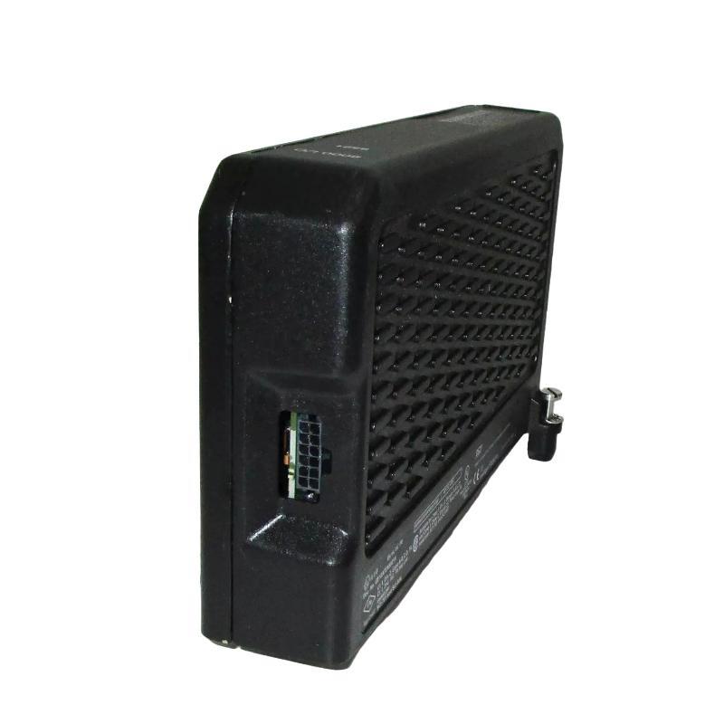
Recognizing GE 8521-RT-DE Communication Failure Patterns
Different symptoms point toward different areas of the PAC8000 system.
The controller is unreachable over Ethernet. Check the workstation's subnet, controller IP address, physical link, and network routing. If the controller is in an initial configuration state, verify whether it requires the supported BOOTP setup procedure.
The controller is reachable, but SCADA values are stale. Investigate protocol selection, remote device addressing, polling configuration, data mapping, and the SCADA communication driver's status.
Only selected I/O points are unavailable. Examine the affected module's status, channel assignment, field wiring, and controller I/O configuration. A fault limited to one module or group of points is less consistent with a complete Ethernet failure.
Serial communications stop responding. Verify port parameters, wiring polarity where applicable, the connected device's address, and whether the port has been locked by configuration.
These observations establish the direction of the investigation. They should not be treated as proof of a particular failed component until the corresponding checks have been completed.
GE PAC8000 Fault Diagnosis: Trace the Failed Communication Path
Start by determining whether the failure affects the engineering connection, SCADA communication, or local I/O.
If the engineering workstation cannot reach the controller, check the physical network and IP configuration first. Record the controller's address, the workstation's address, and the observed link status. A duplicate IP address or an incorrect subnet can create intermittent or misleading connectivity symptoms.
If the controller remains reachable but the SCADA system cannot read data, inspect the active protocol configuration and the event log. Confirm that the expected device address and data mapping agree with the running project. Where applicable, use the supported PAC8000 diagnostic tools to examine communication counters and error indications.
If only I/O data is affected, inspect the module inventory and I/O communication status before modifying the control strategy. Check whether the affected module has a diagnostic fault or whether the controller configuration references a different module or channel arrangement.
An efficient diagnostic sequence is:
Physical link → IP reachability → Protocol session → Data mapping → I/O status
Advance to the next layer only after the preceding layer has been checked. This makes the Troubleshooting record easier to interpret and reduces the risk of changing unrelated settings.
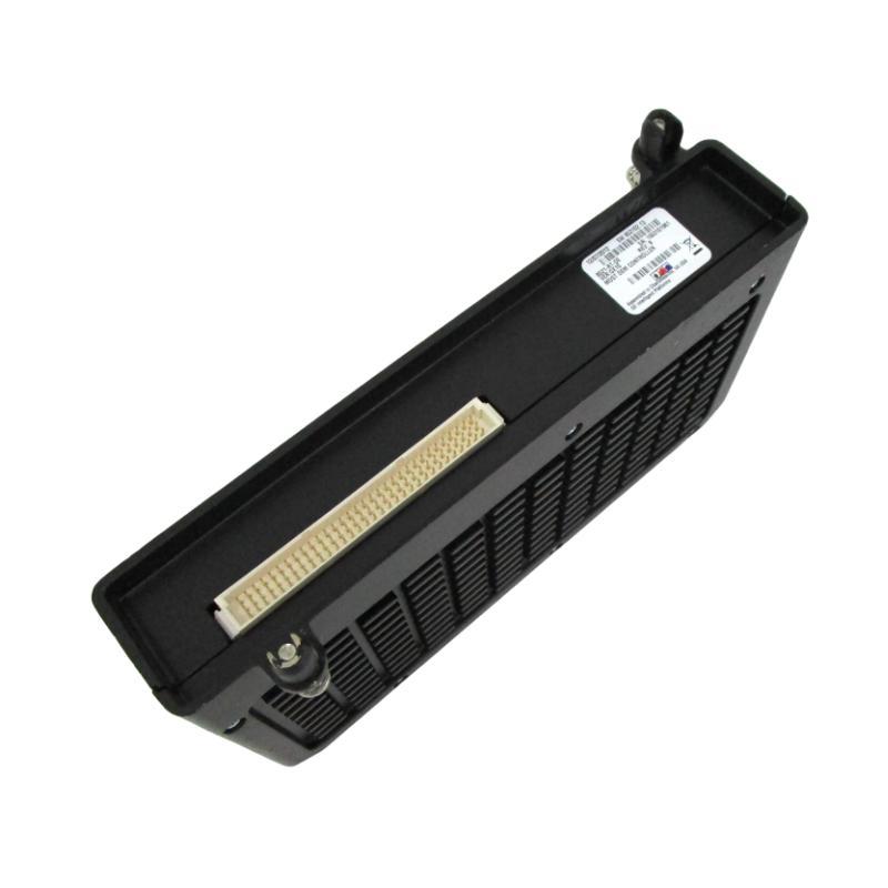
Case Analysis: GE 8521-RT-DE Serial Port Lockout
A specific PAC8000 RTU restriction documented for the 8521-RT-DE concerns serial-port lockout. A locked serial port cannot be unlocked through that same port using the documented procedure. The controller documentation specifies connecting through the other serial port and downloading the I/O configuration to unlock it. If both serial ports are locked, an Ethernet connection can be used to download the I/O configuration; the Network Configurator can also be used to issue the supported port-unlock command over Ethernet.
This failure pattern is important because repeated attempts to communicate through the locked port will not address the underlying restriction.
For Fault Diagnosis, first establish whether the failure is isolated to one serial port or affects both. Verify Ethernet connectivity before attempting recovery. Then use the applicable PAC8000 configuration utility and the approved configuration file to restore access.
This recovery method should be performed by personnel authorized to modify the controller configuration. Confirm the port-lockout state and the correct configuration before downloading anything to a live control system.
PAC8000 Controller Firmware and I/O Communication Faults
Firmware compatibility can also affect the interpretation of communication problems. GE's PAC8000 RTU firmware 2.14 release notes describe corrections involving I/O module recovery, Ethernet LAN A behavior under certain heavy-traffic network conditions, and Modbus write-coil requests involving a value of zero.
These documented issues demonstrate why firmware history should be included in Fault Diagnosis rather than treating all communication failures as wiring problems.
For example, if a module remains failed after a severe diagnostic error, review the controller firmware release and the relevant module firmware requirements. If a Modbus command intended to reset a coil does not take effect, verify the actual request, protocol response, point mapping, and firmware applicability before concluding that the controller output hardware has failed.
Firmware updates should not be the first response to an unexplained communication alarm. Record the current version, preserve the running configuration, confirm compatibility, and follow the manufacturer's upgrade and recovery instructions.
Field Troubleshooting Example: Controller Online but Process Values Are Frozen
Consider a representative maintenance case in which the GE 8521-RT-DE remains accessible from the engineering workstation while the SCADA display continues to show unchanged analog values.
The engineer first confirms that Ethernet connectivity is stable. The next check is whether the SCADA driver is receiving fresh protocol responses rather than displaying cached values. If responses are being received, the investigation moves to point addressing, register mapping, and the controller's live process values.
If the controller's own diagnostic view shows changing values but SCADA does not, the likely investigation area is the communication or mapping path between the controller and the supervisory system. If both views show unchanged values, examine the field signal, I/O channel status, and the application logic.
For an analog input, compare the actual electrical signal with the configured range and displayed engineering value. For a 4–20 mA input, for instance, a measured 12 mA corresponds to 50% of the nominal signal span. That calculation is useful only when the channel is configured for the corresponding 4–20 mA range and scaling.
This is a diagnostic example, not a verified field-service report. No measured recovery time or customer-specific result is claimed.
Restoring GE 8521-RT-DE RTU Operation Safely
After the cause has been isolated, apply the smallest corrective action that addresses the confirmed fault. Correct network parameters when addressing is wrong, restore the intended protocol settings when the communication configuration is inconsistent, and repair field wiring when electrical checks identify a connection problem.
Before downloading a revised configuration, verify that it matches the installed hardware and the approved control strategy. Before restarting the controller, determine whether the restart will interrupt outputs, communications, or remote control functions. Obtain the required operational authorization and place the process in a safe condition.
After recovery, verify the original failure condition, confirm fresh data updates, test affected I/O points, and review the event log for recurring faults. A fault that disappears after a reset but returns during normal operation has not been conclusively resolved.
GE 8521-RT-DE Troubleshooting Keywords and Maintenance Checklist
Engineers investigating a GE 8521-RT-DE PAC8000 RTU Controller communication fault should focus on these long-tail diagnostic areas:
GE 8521-RT-DE Ethernet communication troubleshooting.
PAC8000 RTU serial-port lockout recovery.
GE PAC8000 I/O communication fault diagnosis.
8521-RT-DE firmware compatibility and configuration errors.
PAC8000 Modbus data mapping and SCADA communication faults.
A useful maintenance report should identify the failed communication layer, the observed symptoms, the relevant event-log entries, the firmware and configuration versions, the corrective action, and the post-recovery test results. This provides a repeatable Fault Diagnosis process without assuming that every communication alarm requires controller replacement.

