Allen-Bradley MPL-B680H-MJ74AA Servo Motor Installation and Commissioning Guide
Time:2026-10-16 Browse: 1
Installation Overview of the Allen-Bradley MPL-B680H-MJ74AA Servo Motor
The Allen-Bradley MPL-B680H-MJ74AA servo motor installation process requires correct mechanical alignment, compatible 460 V-class servo drive configuration, feedback wiring, and holding-brake control. This MP-Series low-inertia brushless servo motor features a 215 mm frame, 203.2 mm magnet stack length, 3500 RPM rated speed, multi-turn absolute feedback, and a 24 V DC holding brake. Incorrect feedback configuration or mechanical coupling can prevent successful Setup / Commissioning even when the motor is electrically connected.
Preparing the MPL-B680H-MJ74AA Servo Motor for Installation
Before mounting the motor, verify the nameplate against the machine drawings and confirm that the replacement motor matches the required catalog number. Inspect the housing, keyed shaft, mounting pilot, connectors, and protective packaging for signs of transport damage.
The motor uses a right-angle SpeedTEC DIN connector that can be rotated through 180° according to the manufacturer's installation instructions. Its mounting arrangement uses IEC metric dimensions and free mounting holes of type FF.
Prepare the following before starting:
The MPL-B680H-MJ74AA servo motor.
A compatible Allen-Bradley servo drive and approved motor power, feedback, and brake cables.
The machine's coupling, mounting hardware, and alignment equipment.
The applicable motor installation manual and drive configuration documentation.
The approved electrical isolation and machine safety procedures.
Do not lift or handle the motor by its shaft. The manufacturer also cautions against opening or modifying the motor beyond the connector adjustments described in its installation instructions.
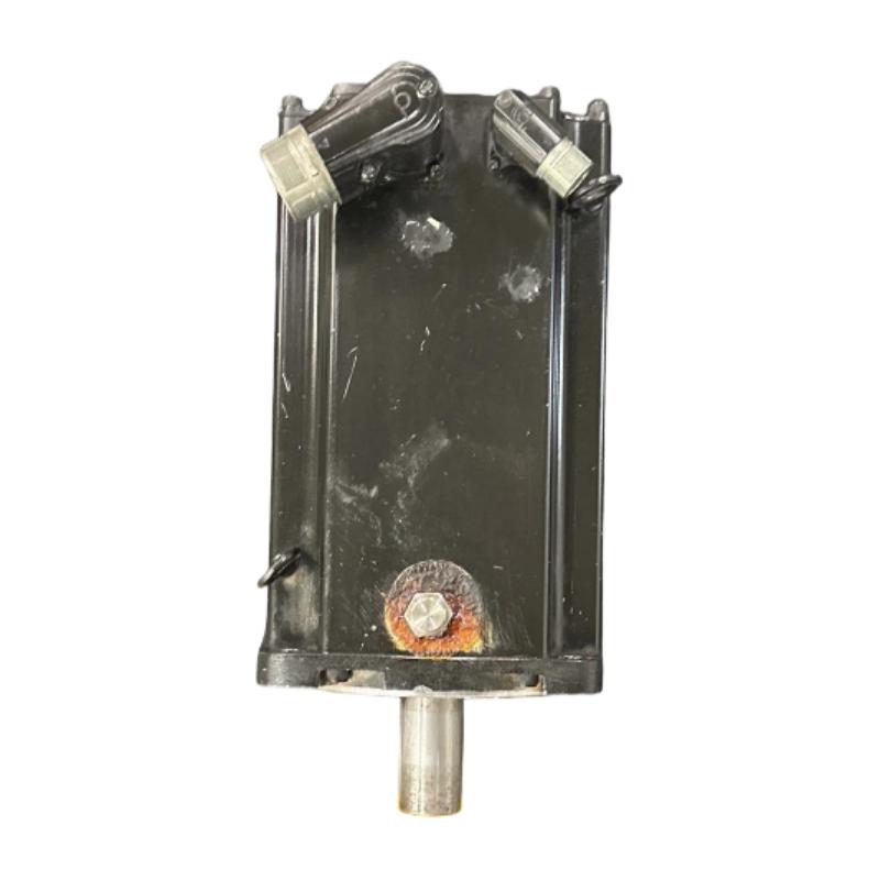
Mechanical Mounting and Shaft Alignment for the MPL-B680H-MJ74AA
Mechanical installation has a direct effect on bearing life, vibration, and positioning accuracy. Clean the mounting surface, inspect the pilot fit, and verify that the motor flange seats correctly before tightening the mounting fasteners to the specified torque.
The keyed shaft must match the coupling or pulley arrangement. Check the key dimensions, coupling compatibility, shaft concentricity, and alignment with the driven machine. Excessive radial or axial loading can shorten bearing life even if the motor operates within its speed rating.
For applications involving belts or gearboxes, compare the actual shaft loads with the manufacturer's allowable radial and axial load ratings at the intended operating speed. Do not assume that a mechanically interchangeable motor has identical load limits.
Electrical Wiring and Feedback Setup for the Allen-Bradley Servo Motor
The MPL-B680H-MJ74AA is a 460 V-class brushless servo motor with multi-turn high-resolution absolute feedback and a 24 V DC holding brake. Confirm that the selected drive supports the motor's feedback interface and the exact catalog number.
During wiring, verify the following:
Motor power: Use the approved motor cable and connector arrangement. Confirm phase connections, grounding, shield termination, and cable compatibility with the drive.
Feedback: Connect the feedback cable to the correct drive interface. Verify that the drive recognizes the absolute feedback device and that the configured motor identity matches the installed motor.
Holding brake: Check the 24 V DC brake circuit and its control logic. The holding brake is intended to hold the load when properly applied; it must not be used as a routine dynamic stopping device unless the system is specifically designed and rated for that duty.
Noise control: Route motor power and feedback cables according to the manufacturer's electromagnetic compatibility recommendations. Keep sensitive feedback wiring separated from high-noise power conductors where required by the installation design.
Before energizing the system, verify the wiring against the approved electrical drawings and confirm that the driven mechanism can be tested safely.
MPL-B680H-MJ74AA Servo Drive Configuration and Commissioning
The Setup / Commissioning process should begin with the drive's motor configuration. Select the correct motor catalog number and verify the feedback type, rated speed, brake settings, and applicable drive parameters.
The motor's documented rated speed is 3500 RPM. This value is a motor specification, not a recommended initial test speed. Initial motion testing should use a conservative speed and acceleration appropriate to the machine and its safety requirements.
With the load secured and the test area clear, confirm that the drive completes its startup checks without feedback or motor identification faults. Where supported, perform the manufacturer's prescribed feedback or motor identification procedure.
Run an initial low-speed test and observe the direction of rotation, actual position feedback, speed response, and motor current. Confirm that the brake releases and applies in the intended sequence. Never assume that a successful motor enable command proves correct mechanical operation.
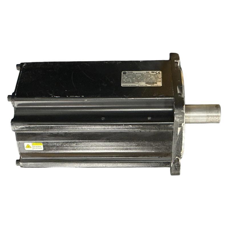
Field Commissioning Example: MPL-B680H-MJ74AA Positioning Error
Consider a representative commissioning situation in which the drive enables successfully but the machine axis does not reach its commanded position accurately.
Rather than replacing the motor immediately, the engineer checks the feedback connection, drive configuration, mechanical coupling, and load movement. If the feedback count changes smoothly but the machine position is incorrect, the investigation shifts toward scaling, coupling slippage, or mechanical backlash. If feedback drops out or produces an encoder-related alarm, the cable, connector, and feedback interface require closer inspection.
This example illustrates an engineering diagnostic method rather than a documented customer installation. Actual positioning error, motor current, and settling time must be measured on the installed machine.
Final Validation of the Allen-Bradley MPL-B680H-MJ74AA
After the initial motion test, verify that the motor follows the commanded direction and speed, that feedback remains stable, and that the brake operates according to the machine sequence.
Record the motor catalog number, drive model, configuration revision, feedback status, and commissioning results. Retain the baseline data for future Troubleshooting and Fault Diagnosis.
For engineers searching for an Allen-Bradley MPL-B680H-MJ74AA Servo Motor Installation Guide, the critical checks are motor-drive compatibility, mechanical alignment, absolute feedback configuration, brake control, and controlled motion validation.

